
Related Manuals for ASROCK 775i65GV


Summary of Contents for ASROCK 775i65GV
-
Page 1: User Manual
775i65GV User Manual Version 1.0 Published July 2004 Copyright©2004 ASRock INC. All rights reserved. -
Page 2: Copyright Notice
(including damages for loss of profits, loss of business, loss of data, interruption of business and the like), even if ASRock has been advised of the possibility of such damages arising from any defect or error in the manual or product. -
Page 3: Table Of Contents
1.1 Package Contents ............5 1.2 Specifications ..............6 1.3 Supported AGP VGA Cards Lists ........8 1.4 Motherboard Layout ............10 1.5 ASRock I/O Plus ............11 2 Installation ............. 12 Pre-installation Precautions ............12 2.1 CPU Installation ..............13 2.2 Installation of CPU Fan and Heatsink ...... - Page 4 4.2 Support CD Information ........... 39 4.2.1 Running Support CD ..........39 4.2.2 Drivers Menu ............39• 4.2.3 Utilities Menu ............39 4.2.4 ASRock “PC-DIY Live Demo” Program ....39 4.2.5 “LGA 775 CPU Installation Live Demo” Program ... 39 4.2.6 Contact Information ..........39...
-
Page 5: Introduction
In case any modifications of this manual occur, the updated version will be available on ASRock website without further notice. You may find the latest memory and CPU support lists on ASRock website as well. ASRock website http://www.asrock.com 1.1 Package Contents... -
Page 6: Specifications
3 PCI slots with PCI Specification 2.2 (see CAUTION 5) AMR slot: 1 slot, supports ASRock MR card (Optional) AGI slot: 1 AGI [ASRock Graphics Interface] slot (see CAUTION 6) USB 2.0: 8 USB 2.0 ports: includes 6 default USB 2.0 ports on the rear panel, plus one header to support 2 additional USB 2.0 ports... - Page 7 PCI card in “PCI3” slot if an AMR card has already been installed in the AMR slot. The AGI [ASRock Graphics Interface] slot is a special design that only supports compatible AGP VGA cards. For the information of the compatible AGP VGA cards, please refer to the “Supported AGP VGA...
-
Page 8: Supported Agp Vga Cards Lists
PROLINK GF4-MX440 SPARKLE GF4-MX440 Gigabyte GV-AP64D Gigabyte GV-AP64D-H Gigabyte GV-AR64S-H POWERCOLOR RADEON 9000 POWERCOLOR RADEON 9100 TRANSCEND TS64MVDR7 SYNNEX GCM-SiS315EA32 For the latest updates of the supported AGP VGA cards list, please visit ASRock website for details. ASRock website: http://www.asrock.com/support/index.htm... - Page 9 Gigabyte GV R9000 PRO Gigabyte RADEON 9500 Gigabyte RADEON 9700 PRO POWER COLOR 9200 SAPHIRE RADEON 9200-128MB POWER COLOR XABRE600 For the latest updates of the supported AGP VGA cards list, please visit ASRock website for details. ASRock website: http://www.asrock.com/support/index.htm...
-
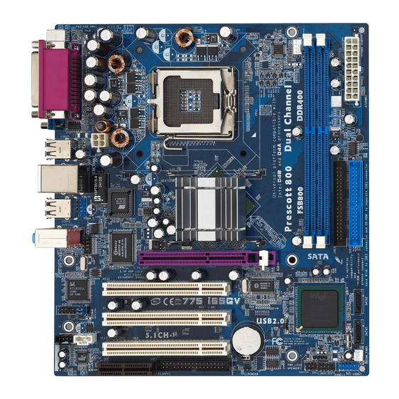
Page 10: Motherboard Layout
Primary IDE Connector (IDE1, Blue) Internal Audio Connector: AUX1 (White) Secondary IDE Connector (IDE2, Black) PCI Slots (PCI1- 3) ASRock Graphics Interface Slot (1.5V_AGP1) JR1 Jumper / JL1 Jumper South Bridge Controller Front Panel Audio Header (AUDIO1) Secondary Serial ATA Connector (SATA2) -
Page 11: Asrock I/O Plus
1.5 ASRock I/O Plus Parallel Port USB 2.0 Ports (USB01) RJ-45 Port USB 2.0 Ports (USB23) Line In (Light Blue) VGA Port Line Out (Lime) PS/2 Keyboard Port (Purple) Microphone (Pink) PS/2 Mouse Port (Green) Shared USB 2.0 Ports (USB45) -
Page 12: Installation
Chapter 2 Installation 775i65GV is a Micro ATX form factor (9.6-in x 8.6-in, 24.4 cm x 21.8 cm) motherboard. Before you install the motherboard, study the configuration of your chassis to en- sure that the motherboard fits into it. Pre-installation Precautions Take note of the following precautions before you install motherboard components or change any motherboard settings. -
Page 13: Cpu Installation
2.1 CPU Installation For the installation of Intel 775-Pin CPU, please follow the steps below. 775-Pin Socket Overview Before you insert the 775-Pin CPU into the socket, please check if the CPU surface is unclean or if there is any bent pin on the socket. Do not force to insert the CPU into the socket if above situation is found. - Page 14 For proper inserting, please ensure to match the two orientation key notches of the CPU with the two alignment keys of the socket. Step 2-3. Carefully place the CPU into the socket by using a purely vertical motion. Step 2-4. Verify that the CPU is within the socket and properly mated to the orient keys.
-
Page 15: Installation Of Cpu Fan And Heatsink
Installation of CPU Fan and Heatsink This motherboard is equipped with 775-Pin socket that supports Intel 775-Pin CPU. Please adopt the type of heatsink and cooling fan compliant with Intel 775-Pin CPU to dissipate heat. Before you installed the heatsink, you need to spray thermal interface material between the CPU and the heatsink to improve heat dissipation. -
Page 16: Installation Of Memory Modules (Dimm)
2.3 Installation of Memory Modules (DIMM) 775i65GV motherboard provides two 184-pin DDR (Double Data Rate) DIMM slots, and supports Dual Channel Memory Technology. For dual channel configuration, you always need to install two identical (the same brand, speed, size and chip-type) memory modules in the DDR DIMM slots to activate Dual Channel Memory Technology. -
Page 17: Expansion Slots (Pci, Amr, And Agi Slots)
PCI card in “PCI3” slot if an AMR card has already been installed in the AMR slot. AMR slot: AMR slot is used to insert an ASRock MR card (optional) with v.92 Modem functionality. -
Page 18: Easy Dual Monitor Feature
2.5 Easy Dual Monitor Feature Thanks to ASRock patented AGI8X Technology, this motherboard supports Easy Dual Monitor upgrade. With the internal onboard VGA and the external add-on AGP VGA card, you can easily enjoy the benefits of Dual Monitor feature. For the... - Page 19 Clear CMOS (CLRCMOS0) 2-pin jumper (see p.10 No. 18) Note: CLRCMOS0 allows you to clear the data in CMOS. The data in CMOS includes system setup information such as system password, date, time, and system setup parameters. To clear and reset the system parameters to default setup, please turn off the computer and unplug the power cord from the power supply.
-
Page 20: Onboard Headers And Connectors
2.7 Onboard Headers and Connectors Onboard headers and connectors are NOT jumpers. Do NOT place jumper caps over these headers and connectors. Placing jumper caps over the headers and connectors will cause permanent damage of the motherboard! FDD connector (33-pin FLOPPY1) FLOPPY1 Pin1 (see p.10 No. - Page 21 SATA power cable to the power connect to the power supply connector of the power supply. USB 2.0 Header ASRock I/O Plus accommo- USB_PWR dates 6 default USB 2.0 ports. If (9-pin USB67) DUMMY those USB 2.0 ports on the I/O (see p.10 No.
- Page 22 PLED+ System Panel Header This header accommodates PLED- PWRBTN# several system front panel (9-pin PANEL1) functions. (see p.10 No. 16) DUMMY RESET# HDLED- HDLED+ Chassis Speaker Header Please connect the chassis SPEAKER speaker to this header. (4-pin SPEAKER 1) DUMMY DUMMY (see p.10 No.
-
Page 23: Serial Ata (Sata) Hard Disks Installation
Serial ATA (SATA) Hard Disks Installation This motherboard adopts Intel ICH5 south bridge chipset that supports Serial ATA (SATA) hard disks. You may install SATA hard disks on this motherboard for internal storage devices. This section will guide you to install the SATA hard disks. STEP 1: Install the SATA hard disks into the drive bays of your chassis. -
Page 24: Bios Setup Utility
Chapter 3 BIOS SETUP UTILITY Introduction This section explains how to use the BIOS SETUP UTILITY to configure your system. The BIOS FWH chip on the motherboard stores the BIOS SETUP UTILITY. You may run the BIOS SETUP UTILITY when you start up the computer. Please press <F2> during the Power-On-Self-Test (POST) to enter the BIOS SETUP UTILITY, otherwise, POST will continue with its test routines. -
Page 25: Navigation Keys
[ :00:09] System Date [Wed 06/30/2004] Use [+] or [-] to configure system Time. BIOS Version : 775i65GV BIOS P1.00 Processor Type : Genuine Intel (R) Pentium (R) CPU 3.20 GHz Processor Speed : 3200 MHz Cache Size : 1024KB... -
Page 26: Advanced Screen
3.3 Advanced Screen In this section, you may set the configurations for the following items: CPU Configuration, Chipset Configuration, ACPI Configuration, IDE Configuration, PCIPnP Configuration, Floppy Configuration, SuperIO Configuration, and USB Configuration. BIOS SETUP UTILITY H/W Monitor Boot Security Exit Main Advanced Configure CPU... -
Page 27: Chipset Configuration
Ratio Status This is a read-only item, which displays whether the ratio status of this motherboard is “Locked” or “Unlocked”. If it shows “Unlocked”, you will find an item Ratio CMOS Setting appears to allow you changing the ratio value of this motherboard. - Page 28 DRAM Frequency If [Auto] is selected, the motherboard will detect the memory module(s) inserted and assigns appropriate frequency automatically. You may also select other value as operating frequency: [133MHz (DDR 266)], [166MHz (DDR 333)], [200MHz (DDR 400)]. Flexibility Option The default value of this option is [Disabled]. It will allow better tolerance for memory compatibility when it is set to [Enabled].
-
Page 29: Acpi Configuration
3.3.3 ACPI Configuration BIOS SETUP UTILITY Advanced ACPI Configuration Select auto-detect or disable the STR feature. Suspend To RAM [Disabled] Restore on AC / Power Loss [Power Off] Ring-In Power On [Disabled] PCI Devices Power On [Disabled] PS / 2 Keyboard Power On [Disabled] RTC Alarm Power On [Disabled]... -
Page 30: Ide Configuration
3.3.4 IDE Configuration BIOS SETUP UTILITY Advanced Set [Compatible Mode] IDE Configuration when both Legacy OS (MS-DOS, Win Me / 98SE) OnBoard IDE Operate Mode [Enhanced Mode] and SATA device OnBoard IDE Controller [Both] are used. Primary IDE Master [Hard Disk] Set [Enhanced Mode] Primary IDE Slave [Not Detected]... - Page 31 IDE Device Configuration You may set the IDE configuration for the device that you specify. We will use the “Primary IDE Master” as the example in the following instruction, which can be applied to the configurations of “Primary IDE Slave”, “Sec- ondary IDE Master”, “Secondary IDE Slave”, “SATA1”...
-
Page 32: Pcipnp Configuration
Block (Multi-Sector Transfer) The default value of this item is [Auto]. If this feature is enabled, it will enhance hard disk performance by reading or writing more data during each transfer. PIO Mode Use this item to set the PIO mode to enhance hard disk performance by optimizing the hard disk timing. -
Page 33: Floppy Configuration
3.3.6 Floppy Configuration In this section, you may configure the type of your floppy drive. BIOS SETUP UTILITY Advanced Floppy Configuration Select the type of floppy drive connected to the Floppy A [1.44 MB 3 "] system. Floppy B [Disabled] Select Screen Select Item Change Option... - Page 34 Parallel Port Address Use this item to set the address for the onboard parallel port or disable it. Configuration options: [Disabled], [378], and [278]. Parallel Port Mode Use this item to set the operation mode of the parallel port. The default value is [ECP+EPP].
-
Page 35: Usb Configuration
3.3.8 USB Configuration BIOS SETUP UTILITY Advanced USB Configuration To enable or disable the onboard USB controllers. USB Devices Enabled : None [Enabled] USB Controller USB 2.0 Support [Enabled] Legacy USB Support [Disabled] Select Screen Select Item Change Option General Help Load Defaults Save and Exit Exit... -
Page 36: Boot Screen
3.5 Boot Screen In this section, it will display the available devices on your system for you to config- ure the boot settings and the boot priority. BIOS SETUP UTILITY Main Advanced H/W Monitor Boot Security Exit Boot Settings Configure Settings during System Boot. -
Page 37: Boot Device Priority
3.5.2 Boot Device Priority In this section, you may specify the boot sequence from the available devices in your system. BIOS SETUP UTILITY Boot Specifies the boot Boot Device Priority sequence from the available devices. [1st FLOPPY DRIVE] 1st Boot Device [HDD: PM-MAXTOR 6L08] 2nd Boot Device A device enclosed in... -
Page 38: Exit Screen
3.7 Exit Screen BIOS SETUP UTILITY Main Advanced H/W Monitro Boot Security Exit Exit Options Exit system setup after saving the changes. Save Changes and Exit Discard Changes and Exit F10 key can be used Discard Changes for this operation. Load Optimal Defaults Select Screen Select Item... -
Page 39: Software Support
Support CD through the following path: ..\ MPEGAV \ LGA775INST.DAT 4.2.6 Contact Information If you need to contact ASRock or want to know more about ASRock, welcome to visit ASRock’s website at http://www.asrock.com; or you may contact your dealer for further information.
Need help?
Do you have a question about the 775i65GV and is the answer not in the manual?
Questions and answers