Table of Contents
Advertisement
Quick Links
Advertisement
Table of Contents

Related Manuals for Busch-Jaeger H8236-5B-03


Summary of Contents for Busch-Jaeger H8236-5B-03
- Page 1 2TMD042400D0022 │ 18.12.2024 System Manual ® Busch-Welcome...
-
Page 2: Table Of Contents
Table of contents Tabl e of contents Overview of IP Technology......................... 7 Cabling and Connection ........................7 1.1.1 Fundamentals of structured cabling ....................7 Network types ..........................11 IP Addressing assignment modes ....................13 1.3.1 Precondition ............................13 1.3.2 Automatic (DHCP) / Manual Mode ....................14 1.3.3 ABB Legacy Mode .......................... - Page 3 Table of contents Outdoor Stations ........................... 91 3.1.1 Preparation ............................91 3.1.2 Installation height ..........................91 3.1.3 The rule of assembled modules......................92 3.1.4 Installation overview .......................... 94 3.1.5 Single column OS ..........................95 3.1.6 Multiple columns OS ........................101 Indoor Stations ..........................
- Page 4 Table of contents Updating the firmware - Single Family Home mode without internet ........... 194 6.3.1 Updating the firmware of the panel via SD card ................194 6.3.2 Updating the firmware of the IP Actuator or the 2nd OS via SD card .......... 197 Updating the firmware - SmartAP with internet ................
- Page 5 Table of contents │5 System Manual 2TMD042400D0022...
- Page 6 Overview of IP Technology │6 System Manual 2TMD042400D0022...
-
Page 7: Overview Of Ip Technology
Overview of IP Technology Overview of IP Technology Cabling and Connection 1.1.1 Fundamentals of structured cabling Structured cabling is a uniform setup plan for a network infrastructure. The network infrastructure is independent of the application and future oriented. Additional designations for the structured cabling are Universal Structured Cabling (UGV) or Universal Communication Cabling (UKV). - Page 8 Overview of IP Technology ISO/IEC 11801 (2002) and EN 50173-1 (2003) │8 System Manual 2TMD042400D0022...
- Page 9 Overview of IP Technology Location distributor Building distributor Floor distributor Connection unit Terminal device Optical fibre Copper conductor Primary area Secondary area Tertiary area Tertiary area including patch cable In the European standard (EN) and the globally valid ISO standard, structuring is carried out in the form of hierarchical levels.
- Page 10 Overview of IP Technology Primary cabling - Site cabling The primary area is designated as campus cabling or site cabling. The primary area implements the joint cabling of individual buildings. The primary area includes large distances, high transmission rates as well as a minimum number of stations. In most cases, glass fibre cable (50 µm) with a maximum length of 1,500 m is used.
-
Page 11: Network Types
Overview of IP Technology Network types For a Welcome IP system there is a distinction between networks: ■ Building Network ■ Private Network Building Network The building network includes all conduits and network components from the outdoor station up to the master indoor station of a unit (apartment or business unit). Main connection network for Welcome IP. - Page 12 Overview of IP Technology The network differentiation is not usually required for Single Family houses, as the entire building is owned and shared, but it is still possible to differentiate if required. It is still possible to share between Building Network/Private to split the network. │12 System Manual 2TMD042400D0022...
-
Page 13: Ip Addressing Assignment Modes
Overview of IP Technology IP Addressing assignment modes 1.3.1 Precondition It is required the installation of the following (or later versions) software version: In case you are not sure which version installed in your components or you face issues during the installation, please use two guides as reference. -
Page 14: Automatic (Dhcp) / Manual Mode
Overview of IP Technology 1.3.2 Automatic (DHCP) / Manual Mode In the Automatic (DHCP) or Manual Mode, the requirement is a router installed and connected to the POE switch which is necessary for the IP address assignation. The advantages of this mode are: ■... - Page 15 Overview of IP Technology The router is required to be connected via LAN cable to the main PoE switch of the System Network (diagram 1 below), or via WIFI from the SmartAP (diagram 2 below). │15 System Manual 2TMD042400D0022...
-
Page 16: Abb Legacy Mode
Overview of IP Technology 1.3.3 ABB Legacy Mode In the ABB Legacy Mode, there is no need for a router to be installed, as it may be used as optional gateway to connect to internet, but it is not required for the IP Addressing assignation. The IP Addressing is automatically generated by Welcome IP, based on the physical addressing of the devices. - Page 17 Overview of IP Technology The recommended set up is to connect the Building Network in the LAN (PoE), while dedicating the Private Network to the LAN (2) port in the SmartAP: │17 System Manual 2TMD042400D0022...
- Page 18 Overview of IP Technology However, it is also possible to connect the router directly to the PoE, or to the LAN (PoE), or to the WiFi of SmartAP: │18 System Manual 2TMD042400D0022...
- Page 19 Overview of IP Technology │19 System Manual 2TMD042400D0022...
-
Page 20: Ports & Services In A Welcome Ip System
Overview of IP Technology 1.3.4 Ports & services in a Welcome IP system Pos : 24 /BJE/Sys tem Manuals/Ü bersicht/Gr undl agen/Strukturier te Ver kabelung -- 03-Ports -- Busch- Welcome IP @ 106\mod_1589611029287_15.doc x @ 1285832 @ @ 1 The following ports & services are used in a Welcome IP system. Port Service 5060, 5070... -
Page 21: Poe Switch Selection
Overview of IP Technology PoE switch selection For selecting a PoE switch, please observe the following points: ■ All Welcome IP devices meet standard IEEE802.3af – Welcome IP devices can be operated with PoE switches that meet standard 802.3af or 802.3at. - Page 22 Overview of IP Technology Example for the selection of a PoE switch Count Device Power consumption (W) IP Touch 7 Lite (LAN+WiFi) 3*9,0=27.0 IP Touch 5 Outdoor Station 10.8 IP Actuator Total output 46.2 Result Number of occupied ports: Necessary total output: 46.2 Recommendation: For the calculation of a reserve for the future, a PoE switch with 8 ports and a total output of 70...
-
Page 23: Overview Of Product Range
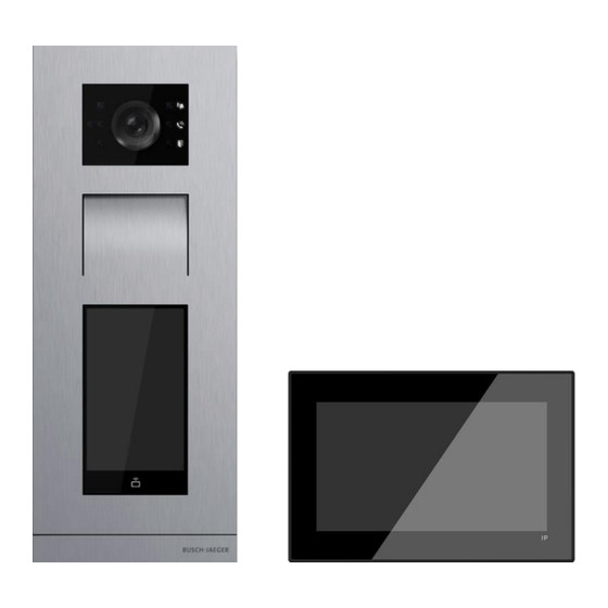
Overview of product range Overview of product range Outdoor Stations 2.1.1 Overview Welcome IP Outdoor Stations are installed in the outdoor areas as follow: ■ Building entrances ■ Perimeter areas ■ Storey areas ■ Apartment doors ■ Basement garages For the door call there is also a voice output aside from the classic doorbell buttons. The voice output can be activated as an option. - Page 24 Overview of product range Type IP Touch 5 OS IP Pushubtton OS Mini OS - IC Video image 720P 720P Camera angle 139° / 111° / 73° 139° / 111° / 73° 139° / 111° / 73° diagonal / horizontal / vertical ●...
-
Page 25: Ip Touch 5 Os
Overview of product range 2.1.2 IP Touch 5 OS Device type Size (WxHxD) Article Product ID Product name Colour number Unit: mm H81381T-S- IP Touch 5 Outdoor Stainless 2TMA130010X0027 135 x 349 x 29 Station steel H81381T- IP Touch 5 Outdoor 2TMA130010W0017 White 135 x 349 x 29... - Page 26 Overview of product range Terminal description Pos : 34 /CND EX/05 Produc t des cripti on/Gl obal IP/T er minal des cripti on_H 8138.T-._IP touch 5 OS @ 93\mod_1563512689585_15.doc x @ 1180745 @ @ 1 Description Reset button Micro USB update connector Plug-in clamps (DC+...GND) for standalone power supply Plug-in clamps (LOCK...GND) for door opener Plug-in clamps (COM...NC...NO) for floating output, door opener...
- Page 27 Overview of product range Technical data Pos : 42 /CND EX/06 T echnic al data/Global IP/T ec hnic al data_H 8138.T-._IP touch 5 OS @ 76\mod_1528861369105_15.doc x @ 940954 @ @ 1 Designation Value 24 V ⎓ Rating voltage 20-27 V ⎓ Operating voltage range 27 V ⎓, 410 mA Rating current...
-
Page 28: Ip Pushbutton Os
Overview of product range 2.1.3 IP Pushbutton OS Device type Pos : 27 /CND EX/03 D evice type/Devi ce type_H 81381P.-._ABB @ 118\mod_1606961388809_15.doc x @ 1407199 @ @ 1 Size (WxHxD) Article Product ID Product name Colour number Unit: mm H81381P1-S- 2TMA130010X0019 Stainless... - Page 29 Overview of product range Terminal description Pos : 34 /CND EX/05 Produc t des cripti on/Gl obal IP/T er minal des cripti on_H 81381P.-._IP pus hbutton OS @ 76\mod_1528860378052_15.doc x @ 940635 @ @ 1 Description Reset button Micro USB update connector Plug-in clamps (DC+...GND) for standalone power supply Plug-in clamps (LOCK...GND) for door opener Plug-in clamps (COM...NC...NO) for floating output, door opener...
- Page 30 Overview of product range Technical data Pos : 42 /CND EX/06 T echnic al data/Global IP/T ec hnic al data_H 81381P.-._IP pus hbutton OS @ 76\mod_1528860416319_15.doc x @ 940656 @ @ 1 Designation Value Rating voltage 24 V DC Operating voltage range 20-27 V DC 27 V DC, 300 mA Rating current...
-
Page 31: Mini Os
Overview of product range 2.1.4 Mini OS Device type Pos : 26 /CND EX/03 D evice type/Devi ce type_H 8131(6).P.-._ABB @ 118\mod_1606963340424_15.doc x @ 1407385 @ @ 1 Size (WxHxD) Article Product ID Product name Colour number Unit: mm H81313P1- 2TMA130010A0003 Mini video outdoor station, Aluminium... - Page 32 Overview of product range Control elements Pos : 30 /CND EX/05 Produc t des cripti on/Gl obal IP/C ontrol el ements _H 8131.P.-._Mi ni OS @ 93\mod_1563776990620_15.doc x @ 1181105 @ @ 1 Description Ring indicator Indicator flashes slowly: ringing Indicator flashes quickly: busy line Call indicator Unlock indicator...
- Page 33 Overview of product range Terminal description Pos : 33 /CND EX/05 Produc t des cripti on/Gl obal IP/T er minal des cripti on_H 8131.P.-._Mi ni OS @ 93\mod_1563777085111_15.doc x @ 1181129 @ @ 1 EXIT AGND LOCK NC COM NO GND DC+ Description Connector for the sensor used for door status detection Connector for exit button...
- Page 34 Overview of product range Technical data Pos : 41 /CND EX/06 T echnic al data/Global IP/T ec hnic al data_H 8131.P.-._Mi ni OS @ 93\mod_1563777209022_15.doc x @ 1181177 @ @ 1 Designation Value 24 V ⎓ Rating voltage 20-27 V ⎓ Operating voltage range 27 V ⎓, 310 mA Rating current...
-
Page 35: Indoor Stations
Overview of product range Indoor Stations 2.2.1 Overview The door call is signalled on the Indoor Station. Here the call is received and the door is opened when a visitor arrives. The camera image is displayed directly, to ensure that you immediately see who is at the door and you can communicate with the visitor. - Page 36 Overview of product range Type IP Touch 7 IP Touch 10 IP Touch Lite 7 Audio IP ● ● ● Touchscreen Extension on app without additional ● ● ● system equipment (prerequisite is an Internet connection) Central operating field for DES, ●...
- Page 37 Overview of product range 2.2.2 IP Touch 7 Device type Pos : 34 /CND EX/03 D evice type/Devi ce type_H 8236_H 8237_ABB @ 110\mod_1597385288514_15.doc x @ 1323517 @ @ 1 Size (WxHxD) Article Order number Product name Colour number Unit: mm H8236-4W- 2TMA130050W0066 IP Touch 7,...
- Page 38 Overview of product range Terminal description Description Power input connector Power input connector (DC-JACK input) Doorbell connector LAN1 (PoE) Micro USB Upgrade connector Extension module connector Microphone Dismantling switch Micro SD card connector Speaker LAN2 Alarm connector RS485 connector, 12 V output, emergency port (SOS, GAS, fire) Relay output IP touch 7 (LAN+LAN) │38...
-
Page 39: Ip Touch 7
Overview of product range Technical data Pos : 48 /CND EX/06 T echnic al data/Global IP/T ec hnic al data_H 8236.-._IP touc h @ 76\mod_1528859299578_15.doc x @ 940288 @ @ 1 Designation Value 24 V ⎓ Rating voltage 20-27 V ⎓ Operating voltage range 27 V ⎓, 250 mA Rating current... - Page 40 Overview of product range 2.2.3 IP Touch 10 Device type Pos : 34 /CND EX/03 D evice type/Devi ce type_H 8236_H 8237_ABB @ 110\mod_1597385288514_15.doc x @ 1323517 @ @ 1 Size (WxHxD) Article Order number Product name Colour number Unit: mm H8237-4W- 2TMA130050W0058 IP Touch 10,...
- Page 41 Overview of product range Terminal description Description Power input connector Power input connector (DC-JACK input) Doorbell connector LAN1 (PoE) Micro USB Upgrade connector Interface module connector Microphone Dismantling switch Micro SD card connector Speaker LAN2 Alarm connector RS485 connector, 12 V output (12 V output is not available when PoE powered) Relay output IP touch 10 (LAN+LAN) │41...
-
Page 42: Ip Touch 10
Overview of product range Technical data Designation Value Rating voltage 24 V ⎓ 20-27 V ⎓ Operating voltage range 27 V ⎓, 390 mA Rating current 24 V ⎓, 440 mA 27 V ⎓, 520 mA Rating current 24 V ⎓, 600 mA Display size 10"... -
Page 43: Ip Touch Lite 7
Overview of product range 2.2.4 IP Touch Lite 7 Device type Pos : 25 /CND EX/03 D evice type/Devi ce type_H 8249_IP T ouc h Li te 7_ABB @ 150\mod_1693275659472_15.doc x @ 1913516 @ @ 1 Size (WxHxD) Article Order number Product name Colour number... - Page 44 Overview of product range Terminal description Pos : 32 /CND EX/05 Produc t des cripti on/Gl obal IP/T er minal des cripti on_H 8249_IP T ouch Li te 7 @ 150\mod_1693275799623_15.doc x @ 1913606 @ @ 1 Description LAN1 (PoE) Doorbell connector Power input connector Speaker...
- Page 45 Overview of product range Technical data Pos : 36 /CND EX/06 T echnic al data/Global IP/T ec hnic al data_H 8249_IP T ouch Li te 7 @ 150\mod_1693275870051_15.doc x @ 1913636 @ @ 1 Designation Value 24 V ⎓ Rating voltage 20-27 V ⎓...
-
Page 46: Audio Ip
Overview of product range 2.2.5 Audio IP Device type Pos : 25 /CND EX/03 D evice type/Devi ce type_H 82001_Audio IP_ABB @ 135\mod_1646699687758_15.doc x @ 1580368 @ @ 1 Size (WxHxD) Article Order number Product name Colour number Unit: mm H82001-W- 2TMA130010W0041 Audio IP, induction loop... - Page 47 Overview of product range Description Call button ■ Pick up the handset in standby mode and press the button to communicate with other indoor stations within the same apartment (default setting). In doing so, all existing indoor stations within the apartment will be called simultaneously. In this case, the group call is stopped as soon as one of the indoor stations accepts the call.
- Page 48 Overview of product range LED Overview Icon Description Red LED always on Blue LED always on Red LED flashes slowly Blue LED flashes slowly Red LED flashes fast Blue LED flashes fast LED status LED status Description "Auto-unlock" function is enabled. Mute the speaker or the microphone.
- Page 49 Overview of product range Terminal description Pos : 32 /CND EX/05 Produc t des cripti on/Gl obal IP/T er minal des cripti on_H 82001_Audio IP @ 135 \mod_1646699844150_15.doc x @ 1580443 @ @ 1 Description A potential-free contact, such as a doorbell Micro SD card slot (only for factory use) LAN (PoE), PoE is the only power supply for this device Reset button...
-
Page 50: System Devices
Overview of product range System devices 2.3.1 Smart Access Point *"Smart Access Point" is usually abbreviated to "SmartAP". The management software is installed on the SmartAP. The SmartAP offers the access point for commissioning and managing the Welcome IP devices with a PC. - Page 51 Overview of product range Terminal description Pos : 30 /CND EX/05 Produc t des cripti on/Gl obal IP/T er minal des cripti on_D 04011 @ 103\mod_1585012532139_15.doc x @ 1257908 @ @ 1 Description USB stick connector (reserved) Tamper switch It is used to prevent intruders breaking into the SmartAP. Once the front shell of the SmartAP is opened, a tamper alert will be sounded by the built-in speaker of the SmartAP.
- Page 52 Overview of product range Status indicator LED Description Blue Green White Priority Flashing Reset to factory default 7 (Highest) slowly Flashing Alarm (e.g. tamper alarm) quickly Power on or initial setup Flashing WiFi Access Point is enabled slowly Security mode is disabled Doorbell is muted Normal operation │52...
- Page 53 Overview of product range Technical data Pos : 34 /CND EX/06 T echnic al data/Global IP/T ec hnic al data_D 04012 @ 79 \mod_1534727635154_15.doc x @ 1044671 @ @ 1 Designation Value 24 V ⎓ Rating voltage 20-27 V ⎓ Operating voltage range 24 V ⎓, 375 mA Rating current...
-
Page 54: Guard Unit
Overview of product range 2.3.2 Guard Unit For the Guard Unit a similar range of functions is available as for the Indoor Station. The concierge can transfer the call to an Indoor Station or assign the access authorisation himself. The ABB-Welcome® App function and Smart Home are not possible for the concierge station. Device type Pos : 26 /CND EX/03 D evice type/Devi ce type_H 8303_GU_ABB @ 126\mod_1620441880016_15.doc x @ 1478597 @ @ 1 Size (WxHxD) - Page 55 Overview of product range Terminal description Pos : 33 /CND EX/05 Produc t des cripti on/Gl obal IP/T er minal des cripti on_H 8303_Guard unit @ 76 \mod_1528877925295_15.doc x @ 941170 @ @ 1 Description Power input connector Power input connector (DC-JACK input) Fire control input (release all the locks in case of emergency) LAN (PoE) Microphone...
- Page 56 Overview of product range │56 System Manual 2TMD042400D0022...
-
Page 57: Ip Actuator
Overview of product range 2.3.3 IP Actuator The "IP actuator" connects the door openers or the lighting, it carries out the switching commands. The settings e.g. the switching duration of the lock release or the switching on of the lighting can be made via the "Indoor Station"... - Page 58 Overview of product range Technical data Pos : 38 /CND EX/06 T echnic al data/Global IP/T ec hnic al data_H 8304_IP actuator @ 87\mod_1553503714701_15.doc x @ 1134107 @ @ 1 Designation Value 24 V ⎓ Rating voltage 20-27 V ⎓ Operating voltage range 27 V ⎓, 310 mA Rating current...
-
Page 59: Ip Elevator Controller & Lift Control Relay Module
Overview of product range 2.3.4 IP Elevator Controller & Lift Control Relay Module The "IP Elevator Controller" & "Lift Control Relay Module" together ensure that elevator only goes to authorised floor(s). If a resident presses the "unlock" button when receiving a guest's call from the outdoor station, or the authorised user swipes the registered card or enters correct password, the elevator will automatically go down to the floor where the outdoor station is installed. - Page 60 Overview of product range Terminal description - IP Elevator Controller Pos : 30 /CND EX/05 Produc t des cripti on/Gl obal IP/T er minal des cripti on_H 8308_IP Elevator c ontroll er @ 144\mod_1667349716621_15.doc x @ 1674775 @ @ 1 Description System power supply connector RS485 connector...
- Page 61 Overview of product range Terminal description - Lift Control Relay Module Description Power supply connector Elevator control module connector Relay output Connect to the elevator keyboard Power LED Module address The module address can be set to 1-16 (only the left 4 bits are used). Status LED Blinks when working normally Product label...
- Page 62 Overview of product range Technical data - IP Elevator Controller Pos : 34 /CND EX/06 T echnic al data/Global IP/T ec hnic al data_H 8308_IP Elevator c ontroll er @ 144 \mod_1667349944123_15.doc x @ 1674801 @ @ 1 Designation Value 24 V ⎓...
-
Page 63: Interface Module
Overview of product range 2.3.5 Interface module Device type Size (WxHxD) Article Order number Product name Colour number Unit: mm 52361EX-03 2TMA130160B0138 Interface Module 16.5 x 60 x 82 Terminal description Description LAN2 Alarm input Relay out *2 RS485 connector, 12 V output, emergency port (SOS, GAS, FIRE) Connector for IP touch │63 System Manual 2TMD042400D0022... - Page 64 Overview of product range Technical data Designation Value ⎓ Rating voltage 24 V ⎓ Operating voltage range 20-27 V ⎓ 27 V , 150 mA Rating current ⎓ 24 V , 170 mA -10 °C…+55 °C Operating temperature ⎓ Power supply output 12 V , 200 mA ⎓...
-
Page 65: Power Supply
Overview of product range 2.3.6 Power Supply Power supply supplies the power for the devices on the system. Device type Pos : 26 /CND EX/03 D evice type/Devi ce type_H 8303_GU_ABB @ 126\mod_1620441880016_15.doc x @ 1478597 @ @ 1 Size (WxHxD) Article Product ID Product name... -
Page 66: Outdoor Station Modules
Overview of product range Outdoor Station Modules 2.4.1 Overview Article number Product name H85138.M-S-03 A/V Module H85138.DP-03 Touch 5" Module 5138.CR-03 Display Module 5138.K-.-03 Keypad Module 5138.RP. -03 Round Pushbutton Module 5138.SP. -03 Bar Pushbutton Module 51381DN-03 Info Module │66 System Manual 2TMD042400D0022... -
Page 67: A/V Module
Overview of product range 2.4.2 A/V Module Device type Size (WxHxD) Article Order number Product name Colour number Unit: mm H851381M- 2TMA130160B0090 A/V Module 96 x 143 x 28 S-03 Control elements Description Camera Speaker and microphone │67 System Manual 2TMD042400D0022... - Page 68 Overview of product range Terminal description Description Reset button Micro USB update connector Plug-in clamps (DC+...GND) for standalone power supply Plug-in clamps (LOCK...GND) for door opener Plug-in clamps (COM...NC...NO) for floating output Network connector (PoE) Connector for next module Connector for exit button Connector for the sensor used for door status detection Connector for big display module │68...
- Page 69 Overview of product range Technical data Designation Value Rating voltage 24 V ⎓ 20-27 V ⎓ Operating voltage range 27 V ⎓, 290 mA Rating current 24 V ⎓, 320 mA -40 °C…+55 °C Operating temperature Camera type CMOS Camera viewing angle 130°...
-
Page 70: Touch 5" Module
Overview of product range 2.4.3 Touch 5" Module Device type Size (WxHxD) Article Order number Product name Colour number Unit: mm H851381DP 2TMA130160B0091 Touch 5" Module 96 x 143 x 23 Control elements Description Touch screen │70 System Manual 2TMD042400D0022... - Page 71 Overview of product range Terminal description Description Connector for previous module Connector for A/V module Connector for Wiegand output It supports 26 bits and 34 bits Connector for next module Technical data Designation Value Rating voltage 24 V ⎓ Operating voltage range 20-27 V ⎓...
-
Page 72: Display Module
Overview of product range 2.4.4 Display Module Device type Size (WxHxD) Article Order number Product name Colour number Unit: mm 51381CR-03 2TMA130160N0030 Display Module, ID 97 x 72 x 25 51382CR-03 2TMA130160N0029 Display Module, Desfire/IC 97 x 72 x 25 Control elements │72 System Manual 2TMD042400D0022... -
Page 73: Keypad Module
Overview of product range Terminal description Description Program button Connector for previous module Connector for device software update Connector for Wiegand output It supports 26 bits and 34 bits Connector for next module Technical data Designation Value 24 V ⎓ Rating voltage 20-27 V ⎓... - Page 74 Overview of product range Size (WxHxD) Article Order number Product name Colour number Unit: mm 51381K-S- 2TMA130160X0023 Stainless Keypad Module 97 x 72 x 25 steel 51381K-W- 2TMA130010W0018 Keypad Module White 97 x 72 x 25 Control elements │74 System Manual 2TMD042400D0022...
-
Page 75: Round Pushbutton Module
Overview of product range Terminal description Description Program button Connector for previous module Connector for device software update (can only be done at the factory) Micro USB update connector Connector for next module Technical data Designation Value 24 V ⎓ Rating voltage Operating voltage range 20-27 V ⎓... - Page 76 Overview of product range Size (WxHxD) Article Order number Product name Colour number Unit: mm 51382RP1- 2TMA130160N0026 Round Pushbutton Module, 1 button, 97 x 72 x 25 Desfire/IC 51382RP2- 2TMA130160N0027 Round Pushbutton Module, 2 button, 97 x 72 x 25 Desfire/IC 51382RP3- 2TMA130160N0028...
- Page 77 Overview of product range Terminal description Description Connector for previous module Connector for next module Program button Connector for device software update Connector for Wiegand output It supports 26 bits and 34 bits 51382RP Technical data Designation Value 24 V ⎓ Rating voltage 20-27 V ⎓...
-
Page 78: Bar Pushbutton Module
Overview of product range 2.4.7 Bar Pushbutton Module Device type Size (WxHxD) Article Order number Product name Colour number Unit: mm 51381SP3- 2TMA130160N0021 Bar Pushbutton Module, 97 x 72 x 25 3/6 buttons 51381SP4- 2TMA130160N0022 Bar Pushbutton Module, 97 x 72 x 25 4/8 buttons Control elements │78... - Page 79 Overview of product range Terminal description Description Connector for previous module Connector for next module Technical data Designation Value 24 V ⎓ Rating voltage 20-27 V ⎓ Operating voltage range 27 V ⎓, 8 mA Rating current 24 V ⎓, 8 mA -40 °C…+55 °C Operating temperature │79...
-
Page 80: Info Module
Overview of product range 2.4.8 Info Module Device type Size (WxHxD) Article Order number Product name Colour number Unit: mm 51381DN-03 2TMA200160N0038 Info Module 97 x 72 x 25 Control elements Terminal description Description Connector for previous module Connector for next module Technical data Designation Value... - Page 81 Overview of product range │81 System Manual 2TMD042400D0022...
-
Page 82: Installation Materials
Overview of product range Installation materials 2.5.1 Video Outdoor Station frame Overview Article number Product name 41383CF-.-03 Video OS frame, size 1/3 41384CF-.-03 Video OS frame, size 1/4 41385CF-.-03 Video OS frame, size 1/5 41386CF-.-03 Video OS frame, size 2/3 41388CF-.-03 Video OS frame, size 2/4 413810CF-.-03... - Page 83 Overview of product range Device type Size (WxHxD) Article Order number Product name Colour number Unit: mm 41383CF-A- 2TMA200160A0003 Video OS frame, size 1/3 Aluminium 135 x 277 x 20.5 41384CF-A- 2TMA200160A0005 Video OS frame, size 1/4 Aluminium 135 x 349 x 20.5 41385CF-A- 2TMA200160A0007 Video OS frame, size 1/5...
-
Page 84: Surface-Mounted Box
Overview of product range 2.5.2 Surface-mounted box Overview Article number Product name 42491S-.-03 Surface-mounted box for IP Touch Lite 7 42361S-.-03 Surface-mounted box for IP Touch 7 42371S-.-03 Surface-mounted box for IP Touch 10 41381S-.-03 Surface-mounted box for OS, size 1/1 41382S-.-03 Surface-mounted box for OS, size 1/2 41383S-.-03... - Page 85 Overview of product range Device type Size (WxHxD) Article Order number Product name Colour number Unit: mm 42491S-W- 2TMA320160W0001 Surface-mounted box for White 188 x 123 x 14 IP Touch Lite 7 42491S-B- 2TMA320160B0001 Surface-mounted box for Black 188 x 123 x 14 IP Touch Lite 7 42361S-W- 2TMA130160W0021...
-
Page 86: Flush-Mounted Box
Overview of product range 2.5.3 Flush-mounted box Overview Article number Product name 42491F-.-03 Flush-mounted box for IP Touch Lite 7 42361F-.-03 Flush-mounted box for IP Touch 7/10 41381F-.-03 Flush-mounted box for OS, size 1/1 41382F-.-03 Flush-mounted box for OS, size 1/2 41383F-.-03 Flush-mounted box for OS, size 1/3 41384F-.-03... - Page 87 Overview of product range Device type Size (WxHxD) Article Order number Product name Colour number Unit: mm *Flush-mounted box for IP 42491F-03 2TMA320160B0002 Black 178 x 108 x 52 Touch Lite 7 *Flush-mounted box for IP 42361F-03 2TMA130160B0134 194 x 145 x 55 Touch 7/10 41381F-B- 2TMA130160B0051...
-
Page 88: Pre-Mounting Box
Overview of product range 2.5.4 Pre-mounting box Overview Article number Product name 42491F-.-03 Pre-installation box for IP Touch Lite 7 42361F-.-03 Pre-installation box for IP Touch 7/10 41381F-.-03 Pre-installation box for OS, size 1/1 41382F-.-03 Pre-installation box for OS, size 1/2 41383F-.-03 Pre-installation box for OS, size 1/3 41384F-.-03... - Page 89 Overview of product range Device type Size (WxHxD) Article Order number Product name Colour number Unit: mm Pre-installation box for IP 42491F-03 2TMA320160B0002 Black 178 x 108 x 52 Touch Lite 7 Pre-installation box for IP 42361F-03 2TMA130160B0134 194 x 145 x 55 Touch 7/10 41381PB-03 2TMA130160B0067...
-
Page 90: Accessories
Overview of product range Accessories Outdoor Stations Device type Size (WxHxD) Article Order number Product name Colour number Unit: mm 51381EP-A- 2TMA200160A0037 Stainless End-strip, size 1/x 135 x 19 x 16 steel 51382EP-A- 2TMA200160A0038 Stainless End-strip, size 2/x 235 x 19 x 16 steel Aluminium 51381MT-03... -
Page 91: Installation Guidelines
Installation guidelines Installation guidelines Outdoor Stations 3.1.1 Preparation Please use gloves to protect yourself against cuts. 3.1.2 Installation height (unit: mm) 1.5 m 5 feet │91 System Manual 2TMD042400D0022... -
Page 92: The Rule Of Assembled Modules
Installation guidelines 3.1.3 The rule of assembled modules Rule 1: A/V module should be placed on the top. Rule 2: Bar pushbutton module cannot work with round pushbutton module Rule 3: Only supports 1 Round pushbutton module with NFC │92 System Manual 2TMD042400D0022... - Page 93 Installation guidelines Rule 4: When other module works with Round pushbutton module │93 System Manual 2TMD042400D0022...
-
Page 94: Installation Overview
Installation guidelines 3.1.4 Installation overview Outdoor Station type Installation type Surface-mounted installation Single column OS Flush-mounted installation in solid walls Flush-mounted installation in hollow walls Multiple columns OS Flush-mounted installation in solid walls Surface-mounted installation Mini OS Flush-mounted installation in solid walls Flush-mounted installation in hollow walls Single column OS contains IP Touch 5 OS, IP pushbutton OS , IP keypad OS and other Outdoor Stations assembled with customised modules. -
Page 95: Single Column Os
Installation guidelines 3.1.5 Single column OS Surface-mounted installation with surface-mounted box Surface-mounted with surface-mounted box Befestigungsschrauben : 4 Durchmesser : Φ4 Schraubenlänge : ≥ 25 mm CLIP2 CLIP1 CLIP3 CLIP rule If only 1 round button module is used in place A, CLIP 1 can be inserted from place B, otherwise CLIP 2 should be inserted. - Page 96 Installation guidelines Flush-mounted installation in solid walls 1. Without pre-mounted box CLIP2 CLIP1 CLIP3 CLIP rule If only 1 round button module is used in place A, CLIP 1 can be inserted from place B, otherwise CLIP 2 should be inserted. If 2 round button modules are used in place A &...
- Page 97 Installation guidelines 2. With pre-mounted box CLIP2 CLIP1 CLIP3 CLIP rule If only 1 round button module is used in place A, CLIP 1 can be inserted from place B, otherwise CLIP 2 should be inserted. If 2 round button modules are used in place A &...
- Page 98 Installation guidelines Flush-mounted installation in hollow walls CLIP2 CLIP1 CLIP3 CLIP rule If only 1 round button module is used in place A, CLIP 1 can be inserted from place B, otherwise CLIP 2 should be inserted. If 2 round button modules are used in place A &...
- Page 99 Installation guidelines Dismantling single column OS Mounting tool Dismantling the modules │99 System Manual 2TMD042400D0022...
- Page 100 Installation guidelines Dismantling the name label Replacing the name plate │100 System Manual 2TMD042400D0022...
-
Page 101: Multiple Columns Os
Installation guidelines 3.1.6 Multiple columns OS Flush-mounted installation in solid wall without pre-mounted boxes * applies to 3-column Outdoor Station only Back view of the mounting box Front view of the mounting box Column 1 Column 1 * applies to 3-column Outdoor Station only Front view of the mounting box Back view of the front panel Column 1... - Page 102 Installation guidelines Flush-mounted installation in solid wall with pre-mounted boxes │102 System Manual 2TMD042400D0022...
- Page 103 Installation guidelines * applies to 3-column Outdoor Station only Front view of the pre-mounting box Column 1 Back view of the pre-mounting box Column 1 * applies to 3-column Outdoor Station only Front view of the mounting box * applies to 3-column Outdoor Station only Back view of the front panel Front view of the mounting box Column 1...
- Page 104 Installation guidelines │104 System Manual 2TMD042400D0022...
- Page 105 Installation guidelines Dismantling the multiple columns OS Front view of Outdoor Station │105 System Manual 2TMD042400D0022...
-
Page 106: Indoor Stations
Installation guidelines Indoor Stations 3.2.1 Location │106 System Manual 2TMD042400D0022... -
Page 107: Ip Touch 7
Installation guidelines 3.2.2 IP Touch 7 Product dimension (unit: mm) 198.5 149.8 Installation height 1.50 m (4.9 feet) │107 System Manual 2TMD042400D0022... - Page 108 Installation guidelines Surface-mounted installation This chapter is not suitable for IP Touch 7 (LAN+LAN). 170.8 131.4 120.7 120.7 Global VDE&BS&CN NEMA 83.3 83.3 79.2 NEMA&Italy NEMA Swiss 198 5 . 149 8 . SM box │108 System Manual 2TMD042400D0022...
- Page 109 Installation guidelines Flush-mounted installation in the solid wall with pre-installation box 192 mm 198 5 . 144 mm 149 8 . 3 1 . 3 2 . 54 mm Hole size of the pre-installation box │109 System Manual 2TMD042400D0022...
- Page 110 Installation guidelines Flush-mounted installation in the hollow wall 198 5 . 186.5 186 5 . Ø9x4 149 8 . 5 9 . 6 0 . Hole size of flush-mounted box │110 System Manual 2TMD042400D0022...
- Page 111 Installation guidelines Desktop installation This chapter is not suitable for IP Touch 7 (LAN+LAN). │111 System Manual 2TMD042400D0022...
- Page 112 Installation guidelines Replacing the end strip Dismantling │112 System Manual 2TMD042400D0022...
-
Page 113: Ip Touch 10
Installation guidelines 3.2.3 IP Touch 10 Product dimension (unit: mm) 250.8 Installation height 1.50 m (4.9 feet) │113 System Manual 2TMD042400D0022... - Page 114 Installation guidelines Surface-mounted installation This chapter is not suitable for IP Touch 10 (LAN+LAN). (unit: mm) IP Touch 10 can use the surface-mounted box of IP Touch 10. 120.7 120.7 Global VDE&BS&CN NEMA 83.3 83.3 79.2 NEMA NEMA&Italy Swiss 250 8 . SM box │114 System Manual 2TMD042400D0022...
- Page 115 Installation guidelines IP Touch 10 can also use the surface-mounted box of IP Touch 7. 170.8 131.4 120.7 120.7 Global VDE&BS&CN NEMA 83.3 83.3 79.2 NEMA NEMA&Italy Swiss SM box of IP Touch 7 │115 System Manual 2TMD042400D0022...
- Page 116 Installation guidelines Flush-mounted installation in the solid wall with pre-installation box (unit: mm) 250 8 . 192 mm 144 mm 54 mm 29.4 Hole size of the pre-installation box │116 System Manual 2TMD042400D0022...
- Page 117 Installation guidelines Flush-mounted installation in the hollow wall (unit: mm) 250 8 . 186.5 186.5 Ø9x4 32.1 Hole size of flush-mounted box │117 System Manual 2TMD042400D0022...
- Page 118 Installation guidelines Desktop installation This chapter is not suitable for IP Touch 10 (LAN+LAN). │118 System Manual 2TMD042400D0022...
- Page 119 Installation guidelines Replacing the end strip 4 screws need to be removed. Dismantling │119 System Manual 2TMD042400D0022...
-
Page 120: Ip Touch Lite 7
Installation guidelines 3.2.4 IP Touch Lite 7 Product dimension (unit: mm) 17 2 . Installation height 1.50 m (4.9 feet) │120 System Manual 2TMD042400D0022... - Page 121 Installation guidelines Surface-mounted installation (unit: mm) 120.7 120.7 83.3 83.3 79.2 NEMA & Italy Swiss N MA (America) VDE&BS 187.6 123.3 SM box Screw the mounting bracket to accessory box. It is recommended to lock the positions marked in grey with screws to better secure the device.
- Page 122 Installation guidelines Flush-mounted installation with pre-installation box (unit: mm) 173.2 107.2 Hole size of pre-installation box │122 System Manual 2TMD042400D0022...
- Page 123 Installation guidelines Flush-mounted installation in the hollow wall (unit: mm) Ø6x4 12 3 . 12 0 . Hole size of flush-mounted box │123 System Manual 2TMD042400D0022...
- Page 124 Installation guidelines Desktop installation Dismantling │124 System Manual 2TMD042400D0022...
-
Page 125: Audio Ip
Installation guidelines 3.2.5 Audio IP Product dimension (unit: mm) 20.9 Installation height 1.5 m 5 feet │125 System Manual 2TMD042400D0022... - Page 126 Installation guidelines Surface-mounted installation (unit: mm) 83.3 79.2 NEMA&Italy Global VDE&BS&CN Swiss length range: 120-150 mm Optional Disassemble the upper part from the bottom part by using a screwdriver. Affix the bottom part on the wall. Affix the bottom part on the box. Connect the wires.
-
Page 127: System Devices
Installation guidelines System devices 3.3.1 Smart Access Point │127 System Manual 2TMD042400D0022... -
Page 128: Guard Unit
Installation guidelines 3.3.2 Guard Unit │128 System Manual 2TMD042400D0022... -
Page 129: Ip Actuator And Ip Elevator Controller
Installation guidelines 3.3.3 IP Actuator and IP Elevator Controller │129 System Manual 2TMD042400D0022... -
Page 130: Lift Control Relay Module
Installation guidelines 3.3.4 Lift Control Relay Module (Dismantle) │130 System Manual 2TMD042400D0022... -
Page 131: Configuration Process
Configuration Process Configuration Process Multi Apartment Configuration with the SmartAP 4.1.1 Topology (DHCP) Master IS Master IS PO E Master IS Master IS PO E Internet Optional Master IS Master IS Router (recommend) PO E Smart Access Point Guard Unit Master IS Master IS PO E... -
Page 132: Topology (Legacy)
Configuration Process 4.1.2 Topology (Legacy) Master IS Master IS PO E Master IS Master IS PO E Master IS Master IS PO E Smart Access Point Guard Unit Master IS Master IS PO E Building Outdoor Station Switch IP Actuator Gate Station ■... -
Page 133: Adding Devices Via The Smartap Auto Scan
Configuration Process 4.1.3 Adding devices via the SmartAP auto scan Note Only the devices on the same network segment as the SmartAP can be added via the SmartAP auto scan. ■ Audio IP and IP Elevator Controller cannot be added via the SmartAP auto scan. They should be added via the SmartAP manually. - Page 134 Configuration Process Please follow the steps below: [1] On the "Main Menu" screen, click "Door entry system" to access the corresponding screen. [2] On the "Door Entry System" screen, click " ". [3] Click "√" to continue. │134 System Manual 2TMD042400D0022...
- Page 135 Configuration Process During the search, click "Hide the window" to hide the current pop-up window and " " will flash to indicate the search status. │135 System Manual 2TMD042400D0022...
- Page 136 Configuration Process [4] Search result will be displayed on the screen; click "√" to continue. [5] Click "Trust All" to trust all devices in the system. For more details, see the "Trusting all devices" chapter on page XXX. │136 System Manual 2TMD042400D0022...
- Page 137 Configuration Process [6] The devices will be displayed on the screen if successful. │137 System Manual 2TMD042400D0022...
-
Page 138: Adding Devices Via The Smartap Manually
Configuration Process 4.1.4 Adding devices via the SmartAP manually Pos : 121 /CNDEX/09 Oper ati on/Global IP/D 04011_SmartAP Pr o/Adding the devi ces on manuall y_D 04011 @ 109 \mod_1597218240614_15.doc x @ 1317965 @ @ 1 Note All the devices can be added via the SmartAP manually. ■... - Page 139 Configuration Process [2] On the "Door Entry System" screen, click "Add device". Note The following operations show you to add a subsidiary indoor station. Please adjust your operations according to the actual devices. [3] Select a device type from the drop-down list (e.g. "Indoor station"). [4] Enter the physical address: ■...
-
Page 140: Adding Devices Via The Smartap & App
Configuration Process 4.1.5 Adding devices via the SmartAP & APP Note All the devices can be added via the SmartAP & APP. ■ All the devices to be added via the SmartAP & APP should not be signed by another SmartAP. - Page 141 Configuration Process Adding devices on the APP ■ Please ensure a building structure has been created on APP.. Please follow the steps below: [1] On the designated floor screen, tap the designated room. [2] On the designated room screen, tap " ".
- Page 142 Configuration Process [4] On the "Device" screen, serial number of the device will be displayed. [5] Check the location. [6] Check the device type. [7] Tap "Add" to add a new device. [8] The result is displayed on the screen if successful. Repeat steps 1~7 to add multiple devices.
- Page 143 Configuration Process Importing the building structure from APP to SmartAP Pos : 82 /CND EX/08 C ommissioning/Global IP/H8249_IP T ouch Li te 7/Importi ng the building struc tur e fr om APP to SmartAP_H 8249 @ 150\mod_1694155872896_15.doc x @ 1915243 @ @ 1 ■...
- Page 144 Configuration Process Importing process Please follow the steps below: [1] On the home screen of the SmartAP, click " ". [2] A pop-up window will appear, please keep the window open and do not click "√". [3] On the "Projects" screen of the APP, swipe the designated project name to the right. [4] Tap "...
- Page 145 Configuration Process [9] On the configuration screen of SmartAP, the project name will be displayed on the screen. [10] Click "√". [11] Click "Confirm". │145 System Manual 2TMD042400D0022...
- Page 146 Configuration Process [12] The import result will be displayed. [13] Click "√" to complete the import process. │146 System Manual 2TMD042400D0022...
-
Page 147: Devices Diagnosis
Configuration Process 4.1.6 Devices Diagnosis It is recommended to check the status of all devices to ensure normal use. Access the "Devices Diagnosis" screen Please follow the steps below: [1] On the "Main Menu" screen, click "Preferences". [2] Click "Devices Diagnosis" to access the corresponding screen. │147 System Manual 2TMD042400D0022... - Page 148 Configuration Process Overview of Devices Diagnosis Description Software version of the SmartAP Signature of the SmartAP If the signature of the device which is displayed on the "Signature" column is not the same as the signature of this SmartAP, "Error" will be displayed. IP mode of the SmartAP Click "...
- Page 149 Configuration Process Error diagnosis "Abnormal" will be displayed due to the following problems. ■ The same physical address has been set on different devices ■ The same IP address has been set on different devices ■ IP mode of this device is different from that of the SmartAP ■...
-
Page 150: Managing The Trusted Devices
Configuration Process 4.1.7 Managing the trusted devices For more details, see chapter 10.8 “Managing the trusted devices“ on page 293. │150 System Manual 2TMD042400D0022... -
Page 151: Single House Configuration Without The Smartap
Configuration Process Single House Configuration without the SmartAP 4.2.1 Topology (DHCP) Router IP Actuator LAN1 LAN1 Master IS Subsidiary IS o Switch 2nd OS ■ In this case, no SmartAP is needed. ■ In this case, a router is needed for use. ■... -
Page 152: Topology (Legacy)
Configuration Process 4.2.2 Topology (Legacy) IP Actuator LAN1 LAN1 Master IS Subsidiary IS o Switch 2nd OS ■ In this case, no SmartAP is needed. ■ In this case, all devices are connected to the same network. ■ In this case, 1 2nd confirmed Outdoor Station, 1 IP Actuator and max. 4 Indoor Stations are recommended. -
Page 153: Preparation
Configuration Process 4.2.3 Preparation ■ Please ensure that all the devices have been connected according to the topology before the configuration. ■ Please ensure all the devices have been powered on. ■ Please ensure all the devices have been restored to factory default settings to prevent unknown abnormal results.see chapter 10.5 “Restoring to factory default“... -
Page 154: Configuring The Master Is
Configuration Process 4.2.4 Configuring the Master IS When the IS is powered on the first time or it is restored to factory default settings, it will access the "Setup Wizard". Please follow the steps below: [1] On the "Setup wizard" screen, select the language from the drop-down list. [2] Select the region from the drop-down list. - Page 155 Configuration Process [5] On the "Configuration Mode" screen, select "Panel set-up for single family house", tap " " to see the system topology, system recommended capacity, and you can download the product manual by scanning the QR code on the right. [6] Tap "Continue".
- Page 156 Configuration Process [7] On the "Panel Addressing" screen, select "Master mode". Only one Indoor Station can be set to "Master mode" in the same apartment. [8] Enter the block number, the floor number and the apartment number or accept the default value.
- Page 157 Configuration Process [10] On the "IP Addressing" screen, tap "Edit" to access the corresponding screen. ■ Select the connection type, it can be set to "LAN" or "WiFi". ■ Select the address type, it can set to "DHCP", "Customizable address" or "ABB Legacy". If "ABB Legacy"...
- Page 158 Configuration Process [12] On the "Trusted Devices" screen, check the system recommended capacity again. [13] Tap "Continue". [14] Check the system topology. [15] Tap "Continue" to start searching the devices in the single-family house. │158 System Manual 2TMD042400D0022...
- Page 159 Configuration Process [16] All the related devices are displayed on the list. [17] Tap "Continue". [18] Tap "Continue". │159 System Manual 2TMD042400D0022...
- Page 160 Configuration Process [19] Tap "Trust all". [20] All the related devices will be displayed on the screen. [21] Tap "Continue". │160 System Manual 2TMD042400D0022...
- Page 161 Configuration Process [22] On the "Time & date" screen, you can carry out this setting at this time or tap "Continue" to skip this setting for the moment. [23] On the "MyBuildings portal" screen, you can carry out this setting at this time or tap "Continue"...
- Page 162 Configuration Process [24] There are 4 screens to guide you how to use the panel. [25] Tap "Skip" if you are already familiar with the panel. Note After configuring the Master IS, the 2nd OS and the IPA have both finished their configuration.
-
Page 163: Configuring The Subsidiary Is
Configuration Process 4.2.5 Configuring the Subsidiary IS Please ensure the Master IS has completed the Wizard Setup before continuing the configuration of the Subsidiary IS: Please follow the steps below to continue the configuration of the Subsidiary IS: [1] On the "Setup wizard" screen, select the language from the drop-down list. [2] Select the region from the drop-down list. - Page 164 Configuration Process [5] On the "IP Addressing" screen, tap "Edit" to access the corresponding screen. ■ Select the connection type, it can be set to "LAN" or "WiFi". ■ Select the address type, it can set to "DHCP", "Customizable address" or "ABB Legacy". If "ABB Legacy"...
- Page 165 Configuration Process [7] On the "Time & date" screen, you can carry out this setting at this time or tap "Continue" to skip this setting for the moment. [8] There are 4 screens to guide you how to use the panel. [9] Tap "Skip"...
-
Page 166: Adding New Trusted Devices Via Auto Search
Configuration Process 4.2.6 Adding new trusted devices via auto search IPA and 2nd OS with IC can only release the lock when they have been added to the trusted devices list. If the designated device has not been added to the trusted device list during the "Setup Wizard", you can add them afterwards via auto search. - Page 167 Configuration Process [5] The devices on the same home network will be displayed on the list. ■ "√" means the device has been configured successfully. Otherwise please restore the designated device to the default factory settings. [6] Tap "Continue". [7] Enable the "Trust all devices". │167 System Manual 2TMD042400D0022...
- Page 168 Configuration Process [8] Tap "Trust All". [9] All trusted devices will be displayed on the screen. [10] will be displayed on the right to indicate the 2nd OS with IC or IP Actuator can use the unlock function. │168 System Manual 2TMD042400D0022...
-
Page 169: Adding New Trusted Devices Manually
Configuration Process 4.2.7 Adding new trusted devices manually IPA and 2nd OS with IC can release the lock only when they have been added to the trusted devices list. If the designated device has not been added to the trusted device list during the "Setup Wizard", you can add them manually. - Page 170 Configuration Process [3] Select the device type from the drop-down list. It can be set to "2nd OS", "Private IP actuator" or "Indoor station". [4] Enter the device number. [5] Enter the serial number. [6] Tap "Save & Close". │170 System Manual 2TMD042400D0022...
- Page 171 Configuration Process [7] The designated device has been added to the list. [8] Tap "Trust all devices". [9] Tap "Trust All". │171 System Manual 2TMD042400D0022...
- Page 172 Configuration Process [10] The designated device is now a trusted device, and will be displayed on the right to indicate the 2nd Outdoor Station or the IP Actuator can use the unlock function. [11] "Trust all devices" will be enabled if all devices have been set to trusted. │172 System Manual 2TMD042400D0022...
-
Page 173: Removing The Trusted Device
Configuration Process 4.2.8 Removing the trusted device Please follow the steps below: [1] On the "Trusted Devices" screen, swipe the relevant device to the left. [2] Tap " " to remove the device. Note If the device is removed from the trusted devices list, it cannot use the unlock function any more. -
Page 174: Grouping And Forwarding
Grouping and Forwarding Grouping and Forwarding Grouping Management Function The Grouping call feature allows the multiple calls of different Indoor Stations, independently of their mode, apartment location and type, as long as they all belong to the same Building System. Please follow the steps below: [1] On the "Main Menu"... - Page 175 Grouping and Forwarding [3] Click " + " to add a new group. [4] Drag the designated Indoor Stations to the "Members" section. ■ Maximum 8 Indoor Stations can be supported. [5] Click "Next". │175 System Manual 2TMD042400D0022...
- Page 176 Grouping and Forwarding [6] Select an Indoor Staton as a leader. [7] Click "Next". [8] Drag the designated Outdoor Stations to the "Outdoor Stations" section. ■ If no pushububtton Outdoor Station is selected, please continue step 13. ■ If a pushububtton Outdoor Station is selected, please continue step 9. [9] Tap a Pushbutton Outdoor Station.
- Page 177 Grouping and Forwarding [11] Click "√" to overwirte the existing setting of the pushbutton. [12] "Call Current Group" will be displayed to indicate the grouping call is activated. [13] Click "Next". │177 System Manual 2TMD042400D0022...
- Page 178 Grouping and Forwarding [14] Enter the group name. [15] Click "Save". [16] All the deivces in the group will be displayed on the screen. Click "√". │178 System Manual 2TMD042400D0022...
- Page 179 Grouping and Forwarding [17] Click " " to refresh the screen. [18] The group is displayed on the screen. [19] Manage the group. ■ Click " " to edit the group. ■ Click " " to remove the group. │179 System Manual 2TMD042400D0022...
-
Page 180: Forwarding Call Feature
Grouping and Forwarding Forwarding Call Feature 5.2.1 Forwarding Call for Indoor Stations The Forwarding call feature allows the call destinated to one Indoor Station to be redirected to a determined alternative Indoor Station, directly, in specific time slots, or in case of missing answer within a selected time. - Page 181 Grouping and Forwarding [4] Select the forwarding type. It can be set to "Direct Forwarding" or "No Answer". ■ If "No Answer" is selected, you need to set "Duration", it can be set to "15","20" or "25". The call will be forwarded after the duration time specified. ■...
-
Page 182: Forwarding Call For Guard Units
Grouping and Forwarding 5.2.2 Forwarding Call for Guard Units The Forwarding call feature allows the call destinated to one Guard Unit to be redirected to a determined alternative Guard Unit, directly, in specific time slots, or in case of missing answer within a selected time. - Page 183 Grouping and Forwarding [4] Select the forwarding type. It can be set to "Direct Forwarding" or "No Answer". ■ If "No Answer" is selected, you need to set "Duration", it can be set to "15","20" or "25". The call will be forwarded after the duration time specified. ■...
-
Page 184: Linking Guard Units
Grouping and Forwarding Linking Guard Units All Guard Units except Guard Unit 1 can be linked to Guard Unit 1. After the setting, these Guard Units will ring at the same time as Guard Unit 1 during an incoming call. Please follow the steps below: [1] On the "Door Entry System"... - Page 185 Grouping and Forwarding [4] Tick the check box to enable the function. [5] Click "Save". [6] Click "√". [7] Go back to "Guard Unit" screen, click Guard Unit 1. │185 System Manual 2TMD042400D0022...
- Page 186 Grouping and Forwarding [8] On the Guard Unit 1 screen, click "Info about linked Guard Units". [9] The linked Guard Units will be displayed on the screen. │186 System Manual 2TMD042400D0022...
-
Page 187: Firmware Update
Firmware update Firmware update Updating overview There are 4 scenarios for updating the firmware. Connect to Using SmartAP Reference internet For more details, see chapter 6.2 “Updating the No, Single Family firmware - Single Family Home mode with internet“ on Home mode page 188. -
Page 188: Updating The Firmware - Single Family Home Mode With Internet
Firmware update Updating the firmware - Single Family Home mode with internet 6.2.1 Updating the firmware of the panel online This chapter applies to IP Touch 7, IP Touch 10 and IP Touch Lite 7, not including Audio IP. On the panel, please follow the steps below: [1] On the "Settings"... - Page 189 Firmware update │189 System Manual 2TMD042400D0022...
- Page 190 Firmware update [8] It will take a little while to download the new software. [9] Tick the check box to accept the licence. [10] Tap "OK". ■ If you don’t want to update the firmware, tap "x" to exit. │190 System Manual 2TMD042400D0022...
- Page 191 Firmware update [11] "Installation successful!" will be displayed on the screen if successful. [12] Tap "Close window". │191 System Manual 2TMD042400D0022...
-
Page 192: Updating The Firmware Of The Ip Actuator Or The 2Nd Os Via App
Firmware update 6.2.2 Updating the firmware of the IP Actuator or the 2nd OS via APP On Single Family Home mode, IP Actuator and the 2nd OS should be updated via APP. Please follow the steps below: [1] On the APP "Home" screen of APP, tap "∨". [2] Tap "Firmware upgrade". - Page 193 Firmware update [4] Find the designated 2 OS or IP Actuator, tap " ". ■ Tap " " to view details about the new version. [5] Tap "OK". │193 System Manual 2TMD042400D0022...
-
Page 194: Updating The Firmware - Single Family Home Mode Without Internet
Firmware update Updating the firmware - Single Family Home mode without internet 6.3.1 Updating the firmware of the panel via SD card This chapter applies to IP Touch 7 and IP Touch 10, not including IP Touch Lite 7 and Audio IP. Please ensure that the firmware update file has been stored in the SD card and the SD card has been inserted into the panel. - Page 195 Firmware update │195 System Manual 2TMD042400D0022...
- Page 196 Firmware update [8] It will take a little while to prepare the installation. [9] "Installation successful!" will be displayed on the screen if successful. [10] Tap "Close window". │196 System Manual 2TMD042400D0022...
-
Page 197: Updating The Firmware Of The Ip Actuator Or The 2Nd Os Via Sd Card
Firmware update 6.3.2 Updating the firmware of the IP Actuator or the 2nd OS via SD card The following operations take the 2nd OS as an example. Please follow the steps below: [1] On the "Outdoor Stations" screen of the panel, tap "Read SD card". [2] Select the designated Outdoor Station. - Page 198 Firmware update [5] "Loading…" will be displayed to indicate that the upgrade is in progress. [6] "Push success!" will be displayed if the upgrade is successful. │198 System Manual 2TMD042400D0022...
-
Page 199: Updating The Firmware - Smartap With Internet
Firmware update Updating the firmware - SmartAP with internet 6.4.1 Updating the firmware of SmartAP online If SmartAP can connect to the internet, a pop-up window will appear automatically when there is a new firmware. Please follow the steps below: [1] The latest version will be displayed. - Page 200 Firmware update [4] Updating the firmware. [5] Click "√" to restart SmartAP. │200 System Manual 2TMD042400D0022...
-
Page 201: Updating The Firmware Of Other Devices Online
Firmware update 6.4.2 Updating the firmware of other devices online This chapter applies to all devices of Welcome IP system except SmartAP. The following operations take the 2nd OS as an example. Please follow the steps below: [1] On the designated device screen, click "Online firmware update". [2] Current firmware version will be displayed. -
Page 202: Updating The Public Devices Online In Batches
Firmware update 6.4.3 Updating the public devices online in batches Note Only the devices which are placed on the public areas (e.g. Guard unit, building IPA, network IPA etc.) can be updated via this method. Please follow the steps below: [1] On the configuration screen, click "... -
Page 203: Updating The Firmware - Smartap Without Internet
Firmware update Updating the firmware - SmartAP without internet 6.5.1 Updating the firmware of SmartAP locally Please follow the steps below: [1] On the "Preferences" screen of SmartAP, click "Firmware updates". [2] Click "Transmit firmware to devices". [3] Click "Browse" to add the new firmware. [4] Click "√". - Page 204 Firmware update [5] Updating the firmware. [6] Tick the check box to select the designated firmware. [7] Click "Install firmware". │204 System Manual 2TMD042400D0022...
- Page 205 Firmware update [8] New features will be displayed on the screen, click "√". [9] Updating the firmware. │205 System Manual 2TMD042400D0022...
- Page 206 Firmware update [10] Click "√" to restart SmartAP. │206 System Manual 2TMD042400D0022...
-
Page 207: Updating The Firmware Of Other Devices Locally One By One
Firmware update 6.5.2 Updating the firmware of other devices locally one by one This chapter applies to all devices of Welcome IP system except SmartAP. The following operations take the 2nd OS as an example. Please follow the steps below: [1] On the designated device screen, click "Local firmware update". - Page 208 Firmware update [6] Update status will be displayed. [7] Click "Close" when the update is completed. │208 System Manual 2TMD042400D0022...
-
Page 209: Updating The Firmware Of Other Devices Locally In Batches
Firmware update 6.5.3 Updating the firmware of other devices locally in batches This chapter applies to all devices of Welcome IP system except SmartAP. The following operations take the OS as an example. Please follow the steps below: [1] On the "Device configuration" screen, click a Door Entry System device (e.g. "Outdoor station"). - Page 210 Firmware update [5] Click "Local firmware update". [6] Upload the firmware. [7] Upload the signature. [8] Click "√" to save. │210 System Manual 2TMD042400D0022...
-
Page 211: Smart Home Integration
Smart Home Integration Smart Home Integration For more details about KNX settings, please see the “10.1 KNX settings” chapter of IP touch 7 & 10 product manual. For more details about free@home settings, please see the “10.2 free@home settings” chapter of IP touch 7 &... -
Page 212: Api
API overview The API provides access to a Welcome IP & AccessControl door entry system, enabling control and monitoring functions. This API facilitates querying information about the current configuration of the door entry system, including devices and their status. It provides endpoints with the ability to query and modify the current status of devices and receive updates on changes. -
Page 213: Topology
Topology The topology is as follows (example only): 3rd party Panel Router 3rd party APP Audio IP Switch Smart Access Point (Local API) IP touch 5 Outdoor Station Precondition ■ Ensure the version of "Smart Access Point" should be 6.36 or above. ■... -
Page 214: Enabling Local Api
Enabling local API Please follow the steps below: [1] On the "Preferences" screen, click "Connections & APIs" to access the corresponding screen. [2] Click "Local API & SIP Configuration". [3] Tick the check box to enable the local API function. [4] It is recommended to tick the check box to enable TLS encryption. -
Page 215: Creating A Local Api User
Creating a local API user Please follow the steps below: [1] On the designated user screen, click "Enable" for API access. [2] Enter the user’s password. If the user has not previously set a password, the password entered here will be used as the password to log into local API. [3] Click "√". - Page 216 [4] Local API user is displayed on the screen. │216 System Manual 2TMD042400D0022...
-
Page 217: Sip
SIP overview Session Initiation Protocol (SIP) integration refers to the process of implementing SIP technology in communications systems to enable and enhance Voice over Internet Protocol (VoIP) capabilities. SIP is a signalling protocol used to initiate, maintain and terminate real-time sessions, primarily involving video, voice, messaging and other communications services over IP networks. -
Page 218: Topology
Pos : 5 /CND EX/08 C ommissi oni ng/Gl obal IP/D 04011/Configuri ng Welc ome IP SIP_D 04011 @ 149\mod_1690268143314_15.doc x @ 1861325 @ 333333 @ 4 Topology The topology is as follows (just an example): Smart Access Point Apartment1 3rd party Panel Switch... -
Page 219: Accessing "Sip" Screen On The Smartap
Accessing "SIP" screen on the SmartAP On the "Preference" screen, click "Connections & APIs" to access the corresponding screen. │219 System Manual 2TMD042400D0022... -
Page 220: Configuring The Smartap As Sip Server
Configuring the SmartAP as SIP server In scenarios where a smart access point (AP) acts as a SIP server, the device plays multiple roles within the network infrastructure. Essentially, it acts as both a connectivity point for Wi-Fi devices and a central hub for managing SIP-based communications. Here's a brief description of its functions in this dual role: Connectivity provider: The Smart AP provides wireless network access to connected devices, just like a traditional access point. - Page 221 Please follow the steps below: [1] On the "Connections & APIs" screen, click "Local API & SIP Configuration". [2] Tick the check box to enable the "Local API and SIP connections" function. [3] Tick the check box to enable "Smart Access Point" as the SIP server. [4] Select the communication protocol.
-
Page 222: Creating A Sip Account For Each 3Rd Party Panel
Creating a SIP account for each 3rd party panel 1. Create the SIP accounts one by one Please follow the steps below: [1] On the "Connections & APIs" screen, click "Create and manage SIP accounts". [2] Click "+". │222 System Manual 2TMD042400D0022... - Page 223 [3] The 3rd party panel will be set to "Indoor station" automatically and cannot be modified. [4] Enter the device address (contains block no., floor no. and room no.). [5] The ID will be generated automatically according to the rule and cannot be modified. [6] The alias will be generated automatically according to the rule and can be modified.
- Page 224 2. Creating SIP accounts in batches SIP accounts for the 3rd party panel can be created in batches. ■ At least one Audio IP is used in each apartment. ■ The 3rd party panel should be on the same network with the designated Audio IP. ■...
-
Page 225: Configuring The 3Rd Party Panel
Configuring the 3rd party panel (The addresses are given as an example only, please check the values with your real installation) Please follow the steps below: [1] Enter the SIP account. [2] Enter the SIP password. [3] Enter the server address 10.0.0.1. [4] Select the transport protocol and enter the port. -
Page 226: Configuring Ip Touch 5 Os
Configuring IP touch 5 OS IP touch 5 outdoor station needs to be configured before using the SIP function. 9.7.1 SIP client settings Please follow the steps below: [1] On the designated IP touch 5 outdoor station screen, click "Settings". [2] Click "SIP client settings". -
Page 227: 3Rd Party Door Opener Settings
9.7.2 3rd party door opener settings The 3rd party panel needs to set a button on the device to release the lock on the IP touch 5 Outdoor Station. Please follow the steps below: [1] On the designated IP touch 5 Outdoor Station screen, click "Settings". [2] Click "3rd party door opener settings". -
Page 228: Adding The 3Rd Party Panels To The Name List One By One
9.7.3 Adding the 3rd party panels to the name list one by one It is available for IP touch 5 outdoor station calls the 3rd party panel via keypad directly or name list. Please follow the steps to add the 3rd party panel to the name list: [1] On the designated IP touch 5 outdoor station screen, click "Name list". - Page 229 [5] Select the designated room where the 3rd party panel is positioned. [6] Click "Confirm". [7] The alias name has been displayed on the screen of the IP touch 5 Outdoor Station. │229 System Manual 2TMD042400D0022...
-
Page 230: Adding The 3Rd Party Panels To The Name List In Batches
9.7.4 Adding the 3rd party panels to the name list in batches If there are multiple 3rd party panels that need to be added to the name list, it is recommended to use the import function. Please follow the steps to add the 3rd party panels to the name list in batches: It is recommended to remove all entries before importing. - Page 231 [5] Select the designated rooms. [6] Click "Import". [7] The alias name has been displayed on the screen. Click the name to set the alias name. │231 System Manual 2TMD042400D0022...
-
Page 232: Configuring Audio Ip
Configuring Audio IP Audio IP needs to be configured before using the SIP function. Please follow the steps below: [1] On the designated Audio IP "Settings" screen, click "SIP client settings". [2] The following settings will be filled automatically when "Smart Access Point" is enabled as an SIP server and Audio IP has obtained the certification from "Smart Access Point". -
Page 233: Appendix
Appendix Appendix 10.1 Initial setup of the SmartAP 10.1.1 Accessing the web-based user interface There are 3 options to access the web-based user interface of the SmartAP. 1. By using the Windows UPnP service Precondition ■ There is a DHCP server on the network, e.g. integrated DHCP is used in the router. ■... - Page 234 Appendix Accessing SmartAP (Window 10 system as an example) [1] Click "Start", followed by "Documents", "Network" to access the "Network" screen. [2] Double click the SmartAP icon. Note If the SmartAP icon is not displayed, please check the Windows firewall or ask for help from your IT engineers.
- Page 235 Appendix [3] Switch to Security Login ■ Http connection is insecure. It is recommended to use an https connection. ■ Click "Advanced", followed by "Proceed to .." to access the web-based user interface of SmartAP. (Google Chrome, for example) ■ IP address of SmartAP can be viewed on the page.
- Page 236 Appendix 2. By entering the IP address Precondition You can check the IP address of SmartAP on the router configuration website. Each router usually has its own management web interface where you can obtain the information. Please check your router’s handbook. Accessing SmartAP (Window 10 system as an example) [1] Enter the IP address of SmartAP (e.g.
- Page 237 Appendix 3. By using the WiFi Access Point hotspot Precondition ■ Ensure network settings are obtained from the SmartAP – WLAN name (SSID) – Password – IP address Please open the front shell of SmartAP obtain the data above from the sticker. 105807A7F02D590 Sma rtAP N e tw o rk se tti n g s...
- Page 238 Appendix ■ Ensure the alarm (e.g. tamper alarm) is not activated Note Status indicator LED light priority (in the sequence, high>>middle>>low): Alarm (flash white quickly) >> Initial setup (light white on) >> WiFi Access Point mode is activated (flash red) >> Security mode is activated (light red on) Tamper alarm will be activated if the front cover of SmartAP is open.
- Page 239 Appendix Pos : 27 /CND EX/08 C ommissioning/Global IP/D04011/Acc essi ng SmartAP thr oug h AP mode_D04011_SmartAP Pro @ 95\mod_1569979222628_15.doc x @ 1204249 @ @ 4 Accessing SmartAP (Window 10 system as an example) [1] Click "Internet access" icon. [2] Click the WLAN name (SSID) of SmartAP. [3] Enter the password.
- Page 240 Appendix [6] Enter "192.168.3.1" on the website to access SmartAP. [7] Switch to Security Login ■ Http connection is insecure. It is recommended to use an https connection. ■ Click "Advanced", followed by "Proceed to .." to access the web-based user interface of SmartAP.
- Page 241 Appendix 10.1.2 Initial setup You need to do the initial setup the first time the SmartAP is powered on or the SmartAP is reset to the factory defaults. Follow the steps below on the web-based user interface of the SmartAP. 1.
- Page 242 Appendix 3. Accepting the licence for software. Tick the checkbox to accept the licence. Then click ">" to continue. 4. Accepting data privacy Tick the checkbox to accept the licence. Then click ">" to continue. │242 System Manual 2TMD042400D0022...
- Page 243 Appendix 5. Configuring the location Select the time zone from the drop-down list. 6. Configuring WiFi access point mode settings and the country code It is compulsory to change the password in the initial setup. The password rule is displayed in a pop-up window when you enter the password.
- Page 244 Appendix 7. Selecting the connection type There are 3 options to set the connection type for the SmartAP. ■ Tap " " to view the topology for reference. │244 System Manual 2TMD042400D0022...
- Page 245 Appendix Establish LAN connection If LAN (PoE) is selected, you need to set IP address to establish the LAN connection. By activating the "Obtain IP address automatically" check box, SmartAP will work as a DHCP client. The IP address needs to be assigned from DHCP server (such as router with DHCP enabled).
- Page 246 Appendix Legacy IP network If "Legacy IP" is selected, the default topology is used as follow. ■ LAN (PoE) will be set to 10.0.x.x, LAN (2) will be connected to the router to obtain the IP address. │246 System Manual 2TMD042400D0022...
- Page 247 Appendix 8. Creating the first admin user Enter the username and the password twice to create the first admin user. Note The first admin user cannot be deleted. It manages all other users. │247 System Manual 2TMD042400D0022...
- Page 248 Appendix 9. Selecting the reset option You can select the reset option according to the use scenario. Reset option = Without MyBuildings account ■ If this option is selected, anyone can reset the password for the first admin user by pressing the reset button.
- Page 249 Appendix 10. MyBuildings settings Reset option = Without MyBuildings account If the reset option is set to "Without MyBuildings account", you will access this screen. [1] Click "Skip" to turn to next step if you don’t want to connect to MyBuildings currently. [2] Click "Register here"...
- Page 250 Appendix Reset option = With MyBuildings account If the reset option is set to "With MyBuildings account", you will access this screen. [1] Click "Register here" to access the MyBuildings portal to register an account. [2] Enter the username, password and friendly name, followed by "Connect" to connect to the MyBuildings portal.
- Page 251 Appendix 11. Setting the device name Enter the name for the device and this name will be displayed on the log in screen. 12. Confirming the settings You can check all the settings again on the overview screen. You can click "<" to return to the previous screens to edit the settings.
-
Page 252: Viewing The Signature Of The Device
Appendix 10.2 Viewing the signature of the device 10.2.1 Video IS Please follow the steps below: [1] On the "Settings" screen, tap "About". [2] Tap "Common". [3] Go to the "Signature" section to check the signature. │252 System Manual 2TMD042400D0022... - Page 253 Appendix 10.2.2 IP Touch 5 OS ■ On the home screen, tap " ", followed by [#] [*] [engineering password] [#] to access the "Settings" screen. ■ On the "Settings" screen, tap "Engineering settings", "Help" to view the signature. │253 System Manual 2TMD042400D0022...
- Page 254 Appendix 10.2.3 IP Pushbutton OS This device can be configured on Video IS. IP Pushbutton OS entering engineering mode Please follow the steps below: [1] Power on the IP Pushbutton OS, wait until all 3 LED indicators go out. [2] Press and hold the first pushbutton for 10 seconds until all 3 LED indicators flash. Video IS accessing the "Outdoor Stations"...
- Page 255 Appendix 10.2.4 Mini OS This device could be configured on Video IS. IP Pushbutton OS entering engineering mode Please follow the steps below: [1] Power on the Mini OS, wait until all 3 LED indicators go out. [2] Press and hold the first pushbutton for 5 seconds until all 3 LED indicators flash. Video IS accessing the "Outdoor Stations"...
- Page 256 Appendix 10.2.5 Guard Unit Please follow the steps below: [1] On the "System Settings" screen, tap "About". [2] Go to "Signature" section to check the signature. │256 System Manual 2TMD042400D0022...
- Page 257 Appendix 10.2.6 IP Actuator This device could be configured on Video IS. Please follow the steps below: [1] Press the reset button of the IP Actuator once during normal operation; the LED flashing green means that the IP actuator has entered engineering mode. [2] On the "Settings"...
-
Page 258: Clearing The Signature Of The Device
Appendix 10.3 Clearing the signature of the device The signature will be empty as one of the following scenarios: ■ The device is powered on the first time. The device is restored to factory default settings.see chapter 10.5 “Restoring to factory ■... -
Page 259: Configuring The Physical Address And Ip Mode
Appendix 10.4 Configuring the physical address and IP mode 10.4.1 Video IS Please follow the steps below: [1] On the "Settings" screen, tap "Advanced settings" and enter the advanced password (The system default advanced password is 345678) to access the corresponding screen. [2] On the "Advanced settings"... - Page 260 Appendix [7] Go to the "IP Address" section, tap " ". [8] Select the connection type, it can be set to "LAN" or "WiFi". [9] Select the network type, it can be set to "DHCP", "Customizable address" or "ABB Legacy". ■...
- Page 261 Appendix 10.4.2 Audio IS This device configures the physical address via SmartAP. │261 System Manual 2TMD042400D0022...
- Page 262 Appendix 10.4.3 IP Touch 5 OS Please follow the steps below: [1] On the home screen, tap " ", followed by [#] [*] [engineering password] [#] to access the "Settings" screen. [2] On the "Settings" screen, tap "Engineering settings". [3] On the "Engineering settings" screen, tap "Device attribute" to edit the device type & physical address.
- Page 263 Appendix 10.4.4 IP Pushbutton OS This device could be configured on Video IS. IP Pushbutton OS entering engineering mode Please follow the steps below: [1] Power on the IP Pushbutton OS, wait until all 3 LED indicators go out. [2] Press and hold the first pushbutton for 10 seconds until all 3 LED indicators flash. Video IS accessing the "Outdoor Stations"...
- Page 264 Appendix [6] Select the connection type and edit the physical address. ■ If IP pushbutton OS is connected to the building network, "External IP gateway" should be selected. ■ If IP pushbutton OS is connected to the private network, "Internal IP gateway" should be selected.
- Page 265 Appendix 10.4.5 Mini OS This device can be configured on Video IS. Mini OS entering engineering mode Please follow the steps below: [1] Power on the Mini OS, wait until all 3 LED indicators go out. [2] Press and hold the first pushbutton for 5 seconds until all 3 LED indicators flash. Video IS accessing the "Outdoor Stations"...
- Page 266 Appendix [6] Select the connection type and edit the physical address. ■ If IP pushbutton OS is connected to building network, "External IP gateway" should be selected. ■ If IP pushbutton OS is connected to private network, "Internal IP gateway" should be selected.
- Page 267 Appendix 10.4.6 Guard Unit Please follow the steps below: [1] On the "System settings" screen, click "Engineering settings", enter the engineering password to access the settings. [2] On the "Engineering settings" screen, tap "Local settings". [3] Go to "Device no." section, edit the physical address. [4] Tap "Network settings", select the network type, it can set to "DHCP", "Customizable address"...
- Page 268 Appendix │268 System Manual 2TMD042400D0022...
- Page 269 Appendix 10.4.7 IP Actuator This device could be configured on Video IS. Please follow the steps below: [1] Press the reset button of the IP Actuator once during normal operation; the LED flashing green means that the IP actuator has entered engineering mode. [2] On the "Settings"...
- Page 270 Appendix [5] Select the device type from the drop-down list and enter the device number. [6] Select the connection type and edit the physical address. ■ If IP Actuator is connected to building network, "External IP gateway" should be selected. ■...
-
Page 271: Restoring To Factory Default
Appendix 10.5 Restoring to factory default Note Building address, signature and all parameters will be restored to the factory default settings after the reset operation. │271 System Manual 2TMD042400D0022... - Page 272 Appendix 10.5.1 Video IS Please follow the steps below: [1] Within 2 minutes of powering on the IS, on the "Advanced settings" screen, tap "Panel". [2] Go to the "Reset panel option" section. [3] Tap "Reset to factory setting". [4] Tap "Yes". │272 System Manual 2TMD042400D0022...
- Page 273 Appendix 10.5.2 Audio IS Please follow the steps below: [1] Disassemble the upper part from the bottom part by using a screwdriver. [2] Within 2 minutes of powering on the Audio IP, press and hold the reset button (located on the upper part) for 3 seconds until the 2 LED indicators turn on and then off.
- Page 274 Appendix 10.5.3 IP Touch 5 OS Please follow the steps below: [1] Power on the OS, wait until all 3 LED indicators go out. [2] Within 2 minutes of powering on the OS, press and hold the reset button for 10 seconds until the 3 LED indicators are lit continuously.
- Page 275 Appendix 10.5.4 IP Pushbutton OS Please follow the steps below: [1] Power on the OS, wait until all 3 LED indicators go out. [2] Within 2 minutes of powering on the OS, press and hold the reset button for 10 seconds until the 3 LED indicators are lit continuously.
- Page 276 Appendix 10.5.5 Mini OS Please follow the steps below: [1] Power on the mini OS with IC, wait until all 3 LED indicators go out. [2] Within 2 minutes of powering on the mini OS with IC, press and hold the first pushbutton for 5 seconds until all 3 LED indicators flash.
- Page 277 Appendix 10.5.6 Guard Unit Please follow the steps below: [1] Within 2 minutes of powering on the Guard Unit, on the "Engineering settings" screen, tap "Local settings". [2] Tap "Clear all data". │277 System Manual 2TMD042400D0022...
- Page 278 Appendix 10.5.7 IP Actuator Please follow the steps below: [1] Within 2 minutes of powering on the IP Actuator, press and hold the reset button for 10 seconds until the indicator goes out. [2] After a while, the indicator flashes green again. │278 System Manual 2TMD042400D0022...
- Page 279 Appendix 10.5.8 IP Elevator Controller Please follow the steps below: [1] Within 2 minutes of powering on the IP Elevator Controller, press and hold the reset button for 10 seconds until the indicator goes out. [2] After a while, the indicator flashes green again. │279 System Manual 2TMD042400D0022...
-
Page 280: Resetting The Password For The Primary Admin
Appendix 10.6 Resetting the password for the primary admin Press and hold the reset button for 10 seconds to reset the password for the primary admin and reset AP password in the same time. R e se t b u tto n AP mo d e sw i tch L ED 1. - Page 281 Appendix 2. Reset option = With MyBuildings account If the reset option is set to "With MyBuildings account" in the initial setup, besides entering a new password twice, a verification code is also needed. Note If you have set an email to receive the verification code in the initial setup, you can obtain the verification code sent by email.
-
Page 282: Configuring The Ip Mode
Appendix 10.7 Configuring the IP mode 10.7.1 Viewing the IP mode Please follow the steps below: [1] On the "Preferences" screen, click "Devices Diagnosis". [2] Display the IP mode of the SmartAP. [3] Drag the scroll bar to the right to view the IP mode of the designated device. │282 System Manual 2TMD042400D0022... - Page 283 Appendix 10.7.2 Changing the IP mode from "DHCP" to "Legacy IP" for all devices Changing the IP mode of the SmartAP will change the IP mode of all devices in the system. Please follow the steps below: [1] On the "Preferences" screen, click "Devices Diagnosis". [2] Click "...
- Page 284 Appendix [4] Click "Save" to save the settings. [5] A warning window will pop up to display the notice. [6] Tick the check box if you want to continue. [7] Click "√" to continue. [8] Click "√" to access the SmartAP again. │284 System Manual 2TMD042400D0022...
- Page 285 Appendix [9] On the "Preferences" screen, click "Devices Diagnosis". [10] Click "Refresh All". [11] "ABB Legacy" will be displayed on the screen and all the devices will be available after this change. │285 System Manual 2TMD042400D0022...
- Page 286 Appendix [12] The IP mode of all the devices will be changed to "Legacy IP" at the same time. │286 System Manual 2TMD042400D0022...
- Page 287 Appendix 10.7.3 Changing the IP mode from "Legacy IP" to "DHCP" for all devices Changing the IP mode of the SmartAP will change the IP mode of all devices on the system. Please follow the steps below: [1] On the "Preferences" screen, click "Devices Diagnosis". [2] Click "...
- Page 288 Appendix [4] Click "Save" to save the settings. [5] A warning window will pop up to display the notice. [6] Tick the check box if you want to continue. [7] Click "√" to continue. [8] Click "√" to access the SmartAP again. │288 System Manual 2TMD042400D0022...
- Page 289 Appendix [9] On the "Preferences" screen, click "Devices Diagnosis". [10] Click "Refresh All". [11] "DHCP" will be displayed on the screen and all the devices will be available after this change. │289 System Manual 2TMD042400D0022...
- Page 290 Appendix [12] The IP mode of all the devices will be changed to "DHCP" at the same time. │290 System Manual 2TMD042400D0022...
- Page 291 Appendix 10.7.4 Changing IP mode for the designated device Please follow the steps below: [1] On the "Device Diagnosis" screen, click " ". [2] Changing the IP mode. ■ If "Static address" is selected, you need to enter the IP address manually or accept the default value.
- Page 292 Appendix [4] New IP mode of the designated device will be displayed on the screen. IP mode matching ■ If the IP mode of the SmartAP is set to "DHCP", the IP mode the designated device could be "DHCP" or "Static address". ■...
-
Page 293: Managing The Trusted Devices
Appendix 10.8 Managing the trusted devices 10.8.1 Managing the trusted devices for outdoor station Pos : 125 /CNDEX/09 Oper ati on/Global IP/D 04011_SmartAP Pr o/Managing the trusted devic es for outdoor stati on_D 04011 @ 109\mod_1597218346123_15.doc x @ 1317989 @ @ 1 If you want to release the lock on the outdoor station, you need to check: ■... - Page 294 Appendix [4] Click "Add trusted devices". [5] Tick the check boxes to select the devices to be trusted. [6] Click "√" to confirm. │294 System Manual 2TMD042400D0022...
- Page 295 Appendix [7] The result is displayed on the screen. [8] Click "Save" to save. │295 System Manual 2TMD042400D0022...
- Page 296 Appendix 2. Removing the trusted devices Please follow the steps below: [1] On the "Door Entry System" screen, click "Outdoor stations". [2] Click the designated outdoor station. [3] Scroll down the list and click "List of trusted devices". │296 System Manual 2TMD042400D0022...
- Page 297 Appendix [4] Click the designated devices to select one by one (the selected devices are highlighted in red). [5] Click "Delete selected". │297 System Manual 2TMD042400D0022...
- Page 298 Appendix 10.8.2 Managing the trusted devices for IP actuator Pos : 128 /CNDEX/09 Oper ati on/Global IP/D 04011_SmartAP Pr o/Managing the trusted devic es for IP actuator_D 04011 @ 109\mod_1597218449258_15.doc x @ 1318013 @ @ 1 If you want to release the lock on the IP actuator, you need to check: ■...
- Page 299 Appendix [4] Click "Add trusted devices". [5] Tick the check boxes to select the devices to be trusted. [6] Click "√" to confirm. │299 System Manual 2TMD042400D0022...
- Page 300 Appendix [7] The result is displayed on the screen. [8] Click "Save" to save. │300 System Manual 2TMD042400D0022...
- Page 301 Appendix 2. Removing the trusted devices Please follow the steps below: [1] On the "Door Entry System" screen, click "IP actuator". [2] Click the designated IP actuator. [3] Click "List of trusted devices". │301 System Manual 2TMD042400D0022...
- Page 302 Appendix [4] Click the designated devices to select one by one (the selected devices are highlighted in red). [5] Click "Delete selected". Pos : 129 /CNDEX/99 Auxiliar y tools/++++++++++++++ pag e break +++++++++++++++ @ 57 \mod_1487814735946_0.doc x @ 750979 @ @ 1 │302 System Manual 2TMD042400D0022...
- Page 303 Appendix Pos : 130 /CNDEX/01 Heading/1.1.1 Heading/H eadi ng_Managing the trusted devic es for " Smart Acc ess Point" @ 108\mod_1597210397338_15.doc x @ 1315342 @ 3 @ 1 10.8.3 Managing the trusted devices for the SmartAP Pos : 131 /CNDEX/09 Oper ati on/Global IP/D 04011_SmartAP Pr o/Managing the trusted devic es for " Smart Ac cess Point"_D 04011 @ 109\mod_1597218492774_15.doc x @ 1318037 @ @ 1 1.
- Page 304 Appendix [4] Click "Trust this management software". [5] The result is displayed on the list. [6] Click "√" to save. │304 System Manual 2TMD042400D0022...
- Page 305 Appendix 2. Trusting the designated IP Actuators Please follow the steps below: [1] On the "Door Entry System" screen, click "IP actuator". [2] Click the designated IP actuator. [3] Click "List of trusted devices". │305 System Manual 2TMD042400D0022...
- Page 306 Appendix [4] Click "Trust this management software". [5] The result is displayed on the list. [6] Click "√" to save. Pos : 132 /CNDEX/99 Auxiliar y tools/++++++++++++++ pag e break +++++++++++++++ @ 57 \mod_1487814735946_0.doc x @ 750979 @ @ 1 │306 System Manual 2TMD042400D0022...
- Page 307 Appendix Pos : 133 /CNDEX/01 Heading/1.1.1 Heading/H eadi ng_Emergenc y unloc k @ 108\mod_1597210431559_15.doc x @ 1315367 @ 3 @ 1 10.8.4 Emergency unlock Pos : 134 /CNDEX/09 Oper ati on/Global IP/D 04011_SmartAP Pr o/Emergenc y unloc k_D 04011 @ 109 \mod_1597218547868_15.doc x @ 1318061 @ @ 1 In some emergency cases, you may need to release all public doors.
- Page 308 Appendix Close all public doors Please follow the steps below: [1] On the configuration screen, click "SOS". [2] Enter the password for the current admin user. [3] Click "Lock all public doors". [4] The result status is displayed on the screen. │308 System Manual 2TMD042400D0022...
-
Page 309: Trusting All Devices
Appendix 10.8.5 Trusting all devices There is a simple way to create a trusting list. Please follow the steps below: [1] On the "Main Menu" screen of SmartAP, click "Door Entry System". [2] Click "Trust All". ■ When new devices are added to the system and the physical address of the device is changed, "... - Page 310 Appendix [3] Click "Trust All". [4] Click "√". The following operations will be carried out by using the "Trusting All" function. Device name Operation Gate Station Trust all Indoor Stations and all IP Actuators. Trust all Indoor Stations, Building IP Actuators and Private IP Building Outdoor Station Actuators within this building.
- Page 311 Appendix │311 System Manual 2TMD042400D0022...
- Page 312 Notice Busch-Jaeger Elektro GmbH We reserve the right to at all times make technical changes as well as 58513 Lüdenscheid changes to the contents of this Freisenbergstraße 2 document without prior notice. The detailed specifications agreed upon apply for orders. Busch- busch-jaeger.de...
Need help?
Do you have a question about the H8236-5B-03 and is the answer not in the manual?
Questions and answers