
Related Manuals for Busch-Jaeger Busch-Welcome IP H8303-03


Summary of Contents for Busch-Jaeger Busch-Welcome IP H8303-03
- Page 1 2TMD041800D0020 │ 08.05.2021 Product manual ® Busch-Welcome H8303-03 Guard unit...
-
Page 2: Table Of Contents
Tab le of c ont e nts Notes on the instruction manual ......................4 Safety ..............................4 Intended use ............................4 Environment ............................5 Busch-Jaeger devices ........................ 5 Product description ..........................6 Device type ..........................6 Control elements........................7 Terminal description ........................8 Technical data ............................ - Page 3 Table of contents History ............................. 38 Call forwarding......................... 41 Emergency unlock ........................42 Lock group ..........................45 Alarm record ..........................47 Cyber security ............................ 49 10.1 Disclaimer ..........................49 10.2 Performance and service ......................49 10.3 Deployment guideline....................... 50 10.4 Upgrading..........................50 10.5 Backup/restore ........................
-
Page 4: Notes On The Instruction Manual
Please keep this manual in a safe place. If you pass the device on, also pass on this manual along with it. Busch-Jaeger accepts no liability for any failure to observe the instructions in this manual. -
Page 5: Environment
Busch-Jaeger devices All packaging materials and devices from Busch-Jaeger bear the markings and test seals for proper disposal. Always dispose of the packing materials and electric devices and their components via an authorized collection facility or disposal company. -
Page 6: Product Description
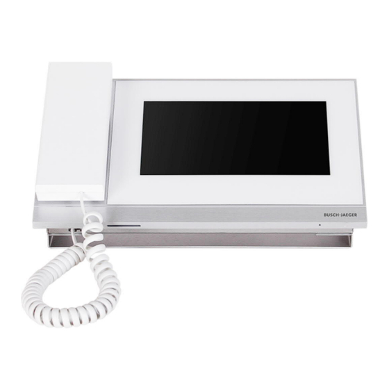
Product description Product description Device type Size (DxHxW) Article Product ID Product name Colour number Unit: mm H8303-03 2TMA130160W0022 Guard unit White 265 x 165 x 117 │6 Product manual 2TMD041800D0020... -
Page 7: Control Elements
Product description Control elements Function Handset Touch screen │7 Product manual 2TMD041800D0020... -
Page 8: Terminal Description
Product description Terminal description Function Power input connector Power input connector (DC-JACK input) Fire control input (release all the locks in case of emergency) LAN (PoE) Microphone Speaker │8 Product manual 2TMD041800D0020... -
Page 9: Technical Data
Technical data Technical data Designation Value Rating voltage 24 V DC Operating voltage range 20-27 V DC 27 V DC, 230 mA Rating current 24 V DC, 260 mA Display size 7" Resolution 1024 x 600 pixel Product dimensions 265 mm × 165 mm × 115 mm Operating temperature -10 °C…+55 °C PoE standard... -
Page 10: Mounting/Installation
Mounting/Installation Mounting/Installation Warning Electric voltage! Dangerous currents flow through the body when coming into direct or indirect contact with live components. This can result in electric shock, burns or even death. – Disconnect the mains power supply prior to installation and/or disassembly! –... -
Page 11: Mounting
Mounting/Installation Mounting │11 Product manual 2TMD041800D0020... -
Page 12: Commissioning
Commissioning Commissioning Initial setup The guard unit enters initial setup automatically when powered on the first time or when "Clear all data" is carried out on the "Engineering settings" screen. Please see the "Local settings" chapter for more details. 1. Select system language │12 Product manual 2TMD041800D0020... - Page 13 Commissioning 2. Accept licensing terms │13 Product manual 2TMD041800D0020...
- Page 14 Commissioning 3. Set date and time │14 Product manual 2TMD041800D0020...
-
Page 15: Enter System Settings
Commissioning Enter System settings On the extra screen, click "System" to access the corresponding screen. │15 Product manual 2TMD041800D0020... -
Page 16: Sound Settings
Commissioning Sound settings On the "System settings" screen, click "Sound" to access the settings. Function Touch sound setting Ringtone setting Click the drop-down list to select the ringtones for outdoor stations, indoor stations, guard unit (4 bulit-in ringtones). Volume settings Adjust the ringtone volume. -
Page 17: Language Settings
Commissioning Language settings On "System settings" screen, click "Language" and select the system language. │17 Product manual 2TMD041800D0020... -
Page 18: Display Settings
Commissioning Display settings On the "System settings" screen, click "Display" to access the corresponding screen. Function Clear screen ■ The countdown (1…30) is displayed on the screen if this function is activated. Any actions on the screen will be invalid. ■... -
Page 19: Date And Time Settings
Commissioning Date and time settings On the "System settings" screen, click "Date and time" to access the corresponding screen. Function Sync time type Tick the checkbox to sync the date and time from the management software automatically. Time and date setting Summer time Tick the checkbox to enable the function. -
Page 20: Monitor Settings
Commissioning Monitor settings On the "System settings" screen, click "Monitor settings", and then click "Download the camera list" to download the camera list from the management software. │20 Product manual 2TMD041800D0020... -
Page 21: Engineering Settings
Commissioning Engineering settings 8.8.1 Enter engineering settings On the "System settings" screen, click "Engineering settings", enter the engineering password to access the settings. Password rule The user must change the engineering password when accessing the engineering settings for the first time. This engineering password must not include increasing or decreasing numbers (e.g. -
Page 22: Local Settings
Commissioning 8.8.2 Local settings Function Device No Range is 1...32. Call mode Toggles the call mode between "Physical address" (default) and "Logical address". The 2nd lock Releases the secondary lock on the outdoor station if the function is enabled. Security mode/Compatible mode The guard unit works in "Security mode"... -
Page 23: Change Password
Commissioning 8.8.3 Change password On the "System settings" screen, click "Password management" to access the settings. Function Change engineering password Click here to change the engineering password (the system default is 345678). Change lock group password Click here to change the lock group password (the system default is 123456). Please see the "Lock group"... -
Page 24: Lock Group
Commissioning 8.8.4 Lock group This function is only available on the guard unit which is set to "Security mode". On the "Engineering settings" screen, click "Lock management" and "Add area" to access the settings. Tick the "Lock group" checkbox to enable the function, select the lock, enter the area name (e.g. "E01") and click "OK"... -
Page 25: Emergency Unlock
Commissioning 8.8.5 Emergency unlock On the "Engineering settings" screen, click "Lock management", then click "Add area" to access the settings. Tick the check box "Emergency" to enable the function, select the lock, enter the area name (e.g. "All") and click "OK" to save. │25 Product manual 2TMD041800D0020... - Page 26 Commissioning Fire linkage This function is only available on the guard unit which is set to "Security mode". On the "Engineering settings" screen, click "Lock management", tick the "Fire linkage" checkbox to enable the function (the system default is disabled). Select lock open type (e.g.
-
Page 27: Reset Settings
Commissioning Reset settings On the "System settings" screen, click "Reset user settings", enter the user password (the system default is 123456) and click "OK" to reset the user settings. │27 Product manual 2TMD041800D0020... -
Page 28: About
Commissioning 8.10 About On the "System settings" screen, click "About" to view the version information. Function Version information Address of the guard unit Serial number This number is used to obtain the certificate from the management software. Signature This number is displayed when the guard unit receives the certificate from the management software successfully. -
Page 29: Add A Contact
Commissioning 8.11 Add a contact On the DES home screen, click to access the corresponding screen. On the "Intercom contacts" screen, click to access the settings. Click "Add contacts" to add a contact. Click "Download contacts" to download the contacts from the management software. Click "Delete All"... -
Page 30: Operation
Operation Operation Incoming call 9.1.1 Call from outdoor station/gate station The guard unit displays the image as full screen by default. Click to switch to normal screen mode. Function Caller ID Display the image of the outdoor stations (the countdown will be displayed in the last 9 s). Click this icon to accept the call. - Page 31 Operation │31 Product manual 2TMD041800D0020...
-
Page 32: Calling From The Guard Unit/Indoor Station
Operation 9.1.2 Calling from the guard unit/indoor station Function Caller ID Display the countdown in the last 9 s. Click this icon to accept the incoming call. Click this icon to mute the ringtone on this device. Click this icon to end the call. Click this icon to mute the volume. -
Page 33: Intercom
Operation Intercom 9.2.1 Accessing the intercom screen In standby mode, click on the DES home screen to access the corresponding screen. │33 Product manual 2TMD041800D0020... -
Page 34: Initiating An Intercom Call
Operation 9.2.2 Initiating an intercom call On the Intercom screen, select a contact, then click to initiate an intercom call You can also click and enter the physical address/logic address, click to initiate an intercom call. │34 Product manual 2TMD041800D0020... -
Page 35: Surveillance
Operation Surveillance In standby mode, on the DES screen, click to start a surveillance. │35 Product manual 2TMD041800D0020... -
Page 36: Surveillance From Outdoor Station/Gate Station
Operation 9.3.1 Surveillance from outdoor station/gate station Function Caller ID Display the image from the outdoor station. (the countdown will be displayed in the last 9 s) End the surveillance. Release the default lock Click this icon to release the default lock of the monitored outdoor station. Release the 2nd lock Click this icon to release the secondary lock of the monitored outdoor station. -
Page 37: Calling Other Guard Unit
Operation 9.3.2 Calling other guard unit In standby mode, click on the DES home screen to enter corresponding screen. Click and entert "#"+ "Guard unit no.", then click to initiate an intercom call. │37 Product manual 2TMD041800D0020... -
Page 38: History
Operation History In standby mode, click on the DES home screen or click on the status bar to access the "History" screen. │38 Product manual 2TMD041800D0020... - Page 39 Operation A maximum of 30 call records can be stored. Highlighting indicates unread status. Click the picture to see details on the pop up window. Click "<" or ">" to view the pictures. (a maximum of 3 pictures for each record) │39 Product manual 2TMD041800D0020...
- Page 40 Operation Click to enter the settings. Click "Delete All" to delete the entire history record. │40 Product manual 2TMD041800D0020...
-
Page 41: Call Forwarding
Operation Call forwarding When the guard unit receives a call from an outdoor station, you can click to access "Call forward" screen, then click to transfer the call to the indoor station. Or you can click then enter the address of the indoor station to transfer the call. │41 Product manual 2TMD041800D0020... -
Page 42: Emergency Unlock
Operation Emergency unlock On the extra screen, click "Emergency unlock" to access the corresponding screen. │42 Product manual 2TMD041800D0020... - Page 43 Operation Click , then enter the emengency unlock password (the system default is 123456), click "OK" to unlock. will be displayed if successful. If you want to lock again, you can click , then enter the emengency unlock password, click "OK"...
- Page 44 Operation Fire alarm If the "Fire linkage" function is used and related to the emergency unlock or lock group, when the alarm is triggered, the guard unit may receive the the message below. │44 Product manual 2TMD041800D0020...
-
Page 45: Lock Group
Operation Lock group On the extra screen, click "Lock group" to access the corresponding screen. │45 Product manual 2TMD041800D0020... - Page 46 Operation Click , then enter the lock group passward (the system default is 123456), click "OK" to unlock. will be displayed if successful. If you want to lock it again, you can click , then enter the lock group password and click "OK"...
-
Page 47: Alarm Record
Operation Alarm record On the extra screen, Click "Alarm record" to access the corresponding screen. A maximum of 100 alarm records is supported. The guard unit will display the alarm message and paly the alarm sound if there is an alarm (e.g. SOS, zone alarm, duress alarm, tamper alarm) is sent from the indoor station or the outdoor station. - Page 48 Operation │48 Product manual 2TMD041800D0020...
-
Page 49: Cyber Security
H8303 product, the network, its system and interfaces against any kind of security breaches, unauthorized access, interference, intrusion, leakage and/or theft of data or information. Busch-Jaeger Ltd and its affiliates are not liable for damages and/or losses related to such security breaches, unauthorized access, interference, intrusion, leakage and/or theft of data or information. -
Page 50: Deployment Guideline
Malware prevention solution The device H8303 is not susceptible to malware, because custom code cannot be executed on the system. The only way to update the software is by firmware upgrading. Only firmware signed by Busch-Jaeger can be accepted. 10.7 Password rule The user must change the engineering password when accessing the engineering settings for the first time. -
Page 51: Notice
We reserve the right to at all times make technical changes as well as changes to the contents of this document without prior notice. The detailed specifications agreed to at the time of ordering apply to all orders. Busch-Jaeger accepts no responsibility for possible errors or incompleteness in this document. - Page 52 Busch-Jaeger Elektro GmbH A member of the ABB Group Freisenbergstraße 2 58513 Lüdenscheid www.BUSCH-JAEGER.de info.bje@de.abb.com Central sales service: Tel.: +49 2351 956-1600 Fax: +49 2351 956-1700 © Copyright 2021 Busch-Jaeger Elektro GmbH All rights reserved...
Need help?
Do you have a question about the Busch-Welcome IP H8303-03 and is the answer not in the manual?
Questions and answers