
Related Manuals for Bosch WR 400-1K B Series


Summarization of Contents
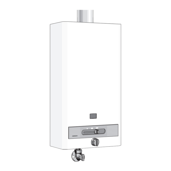
Description of Appliances
Equipment
Lists components such as flame failure device, battery ignition, auto power adaptation, temperature limiter, and draught diverter.
Type Overview
Details multipoint gas water heaters with battery ignition, draught diverters, and automatic gas adaptation by continuous control.
Connecting Measurements
Provides dimensions (A, B, C, D, E, F, G) and gas connection sizes (R1/2", R3/4") for different models.
Constructional Details
Illustrates and lists components of the water heater, including pilot burner, heat exchanger, gas valve, and control unit.
Wiring Diagram
Presents a schematic diagram showing the electrical connections for the appliance components.
Technical Data
Appliance Ratings
Details rated output and input in MJ/h (kW) for WR 250, WR 325, and WR 400 models.
Gas Inlet Pressures
Specifies gas inlet pressures in kPa (mbar) for Natural gas and LP gases.
Gas Consumption
Provides gas consumption rates in m³/h and kg/h for Natural gas and LP gas.
Water Data
Includes max water flow, temperature rise, and minimum inlet water pressure.
Burner Pressure
Details burner pressure settings for maximum and minimum output for Natural gas and LP gases.
Main Burner Injectors
Specifies the diameter of main burner injectors for Natural gas and LP gases.
Pilot Burner Injector
Provides identity numbers for pilot burner injectors for Natural gas and LP gases.
Installation
General Remarks
Emphasizes adherence to local by-laws and regulations for gas-heated appliances.
Location
Recommends frost-protected, well-ventilated rooms, avoiding corrosive substances in combustion air.
Connecting Appliance
Instructions for securing the heater to the wall using supplied mounting brackets.
Removal of Front Shell
Procedure to remove the casing by releasing a retaining nut and pushing upwards.
Water Supply
Guidance on water pipe bore, flushing lines, fitting water filter, and using gate or ball valves.
Gas Connection
Advises sizing the gas supply pipe as per AG601 to avoid warranty voidance.
Flue
Specifies the use of approved single or twin skin flue in accordance with AG601.
Commissioning
Instructions for purging gas piping and restarting the ignition cycle if the pilot fails.
Servicing
Setting Appliance
Notes factory adjustments for LPG (2.75 kPa) and Natural gas (1.11 kPa) heaters.
Gas Adjustments
Details procedures for adjusting burner pressure for maximum and minimum output, and inlet gas pressure.
Conversion to Other Gases
Procedure for converting gas types using manufacturer-supplied kits, involving injector replacement.
Maintenance
Recommends annual inspection, cleaning of heat exchanger, burner, and pilot burner.
Fault Finding
Provides a table listing common problems, their causes, and solutions for appliance malfunction.
Operating Guide - Quick Reference
Functioning
Explains how to operate the appliance using the slide control for gas flow.
Temperature Regulation
Describes how turning the control clockwise or anticlockwise affects water flow and temperature.
Switching Off
Instructs to move the slide control to the far left to turn off the appliance.
Need help?
Do you have a question about the WR 400-1K B Series and is the answer not in the manual?
Questions and answers