
Related Manuals for Flexball 4500 Series


Summarization of Contents
WARRANTY
1. SCOPE OF WARRANTY
Limits of warranty coverage for electronic command systems and their parts.
2. WARRANTY PERIOD
Duration of warranty coverage, measured from shipment or first sea trial.
3. WARRANTY NON EFFECTIVE (Flexball Italiana srl does not warrant)
Conditions and circumstances under which the warranty is not effective.
4. OBLIGATIONS OF USER
User's responsibilities, including inspection, repair, and part usage.
5. WARRANTY REPAIR
Procedure for obtaining warranty repair or periodic inspection.
6. PRODUCT UPGRADE
Flexball Italiana's obligation regarding new specifications.
7. WARRANTY SUCCESSION
Transfer of warranty rights when ownership changes.
1. Introduction
1.1. How to start
Initial steps for system setup and operation after receiving the package.
1.2. System configuration and installer remarks
Details for defining the system setup and remarks for installers.
2. General installation features
2.1. Description of the system and its parts
Overview of the electronic engine remote control system components.
2.2. Maximum extension of the system
Defines the limits for actuators, command stations, and distance.
2.3. System performance
Technical specifications including temperature, humidity, and protection degrees.
3. Pilot instructions
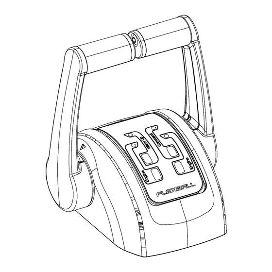
3.1. Control keypad
Explanation of command station buttons, LEDs, and their functions.
3.2. Acquisition of the command
Procedure for taking control of the boat from different command stations.
3.3. Engine Warm-up
Steps for warming up the engine using the control system.
3.4. Single lever mode
How to operate two engines with a single lever.
3.5. Fast Start-up Mode
Functionality for automatic command acquisition upon powering on.
3.6. Emergency lever
Operation of emergency controls for direct manual override of engines/gearboxes.
4. Command Station
4.1. Dimensions
Physical dimensions and mounting details for various command station series.
4.1.5. Removal of the protective cover (when present)
Instructions for removing the command station's protective cover.
4.2. Programming of the command station
Steps to configure the command station for specific installation types.
4.4. Command station label
Information found on the label under the command station base.
4.5. Trolling option
Instructions for activating and using the Trolling function.
4.6. Trim/Flap option
Operation of trim and flap controls from the command station.
4.7. Classification of indoor and outdoor installation
Guidelines for defining command station installation as indoor or outdoor.
4.8. Advices about the mounting and preservation of the command station
Recommendations for mounting and preserving command stations, especially outdoors.
5. Actuator
5.1. Drawing of actuators with mechanical interface
Visual representation and dimensions of actuators with mechanical interface.
5.2. Drawing of full electronic actuator
Visual representation and dimensions of full electronic actuators.
5.3. How to mount the Actuator
Instructions and guidelines for safe and correct actuator installation.
5.4. Electronic actuator boards
Description and pin-outs of various electronic actuator boards.
5.5. Actuator labels and codes
Location and purpose of actuator identification labels for assistance.
6. Accessories and Options
6.1. CANBus cable
Details on CANBus data transmission and extension cables.
6.2. Cables for electronic engine
Various cables for connecting electronic engines and specific brands.
6.3. Cable actuator – gearbox solenoid driven
Cables for connecting actuators to gearbox solenoid systems.
6.4. Cable actuator – trim/flap
Cables for connecting actuators to trim and flap systems.
6.5. Cable actuator –Mercruiser® trim pump
Specific cable for connecting actuators to Mercruiser trim pumps.
6.6. T-Splitter
Accessory for splitting signals, used in system configurations.
6.7. Power supply connector
Connector details for the power supply unit.
7. Configuration of the CANBus network
7.1. Installation with 2 mechanical actuators – solution A
CANBus network setup for systems with 2 mechanical actuators.
7.2. Installation with 2 mechanical actuators – solution B
Alternative CANBus network setup for 2 mechanical actuators.
7.3. Installation with 2 mechanical actuators – solution C
Another CANBus network setup with actuators at network ends.
7.4. Installation with 1 actuator – solution D
CANBus network setup for 1 actuator at the network end.
7.5. Installation with 1 actuator – solution E
CANBus network setup for 1 actuator in the middle of the line.
7.6. Configuration: end of line termination resistor and address setting of command stations and actuators
Setting termination resistors and addresses for network devices.
7.6.2. Configuration of the actuator
Setting actuator dip-switches for CANBus network configuration.
7.7. Configuration with more than 3 command stations
Setup guidelines for CANBus systems with multiple command stations.
7.8. 4600 series switch settings
Specific switch settings for Actuator 4.0 (4600 series).
8. Electrical installation
8.1. Wiring from the battery to the actuator (input cables)
Connecting the power supply from the battery to the actuator.
8.2. Wiring from the actuator to command stations, engines, gearboxes, trim/flaps, etc (output cables)
Connecting actuator output cables to various system components.
9. Programming of the actuator, general guidelines
9.1. Programming keypad
Description of the programming interface and buttons on actuators.
9.2. Display, menus and parameters
Navigating actuator menus and understanding parameter display.
9.3. Actuator parameters
List and explanation of common actuator parameters for tuning.
10. Installation of the push-pull cable and stroke’s programming on the actuator
10.1. Push-pull cables choice
Selection of appropriate push-pull cables and connection kits.
10.2. Mounting of the push-pull cables between engine and actuator
Procedure for connecting push-pull cables to the engine.
10.3. Mounting of the push-pull cable between gearbox and actuator
Procedure for connecting push-pull cables to the gearbox.
11. Programming of the strokes on actuator with mechanical interface to engine and gearbox
11.1. Programming of the push-pull cable strokes
Setting stroke positions for throttle and gearbox via the actuator.
11.2. Sea trials
Verification steps after programming to test system functionality.
11.3. Specific parameters
Detailed parameter settings for various engine types and applications.
12. Programming of actuators for installations with electronic engine and mechanical gearbox
12.1. Programming of the gearbox strokes
Setting gearbox strokes for installations with electronic engines.
12.2. Sea trials
Verification of programming for electronic engine setups.
12.3. Specific parameters
Engine-specific parameters for electronic engines and voltage output signals.
13. Programming of actuators for mechanical engines and electronic gearbox
13.1. Mounting of the engine the push-pull cable and programming of throttle mechanical strokes
Setup for mechanical engines with electronic gearboxes, including cable mounting.
13.2. Programming of the push-pull cable strokes
Setting the stroke positions for mechanical throttles.
13.3. Electrical cabling of the gearbox
Wiring details for electronic gearboxes, referencing relevant sections.
13.4. Specific parameters
Delay parameters for electronic gearboxes during direction changes.
14. Programming of actuators with electronic engine and electronic gearbox
14.1. Electrical wiring
Electrical connections required for electronic engine and gearbox systems.
14.2. Specific parameters
Delay parameters for electronic engine and gearbox systems.
15. Programming of actuators with electronic CANBUS engine and mechanical gearbox
15.1. Installation of the push-pull cable and programming of the cable stroke
Setup for CANBus engines, including cable installation and programming.
15.2. Specific parameters
CANBus related parameters, protocol details, and technical data.
15.3. Wiring of the outgoing actuator cables
Instructions for wiring the outgoing actuator cables.
15.4. Connection to FPT engines through CANBus interface
Connecting to FPT engines using the CANBus interface.
16. Programming of actuators with electronic CANBUS engine and electronic gearbox
16.1. CANBus engine parameters
Configuration of CANBus engine parameters.
16.2. Electronic gearbox parameters
Configuration of electronic gearbox parameters.
16.3. Wiring of the actuator outgoing cables
Connecting actuator output cables.
17. System configuration in case of options
17.1. Commissioning of actuators for installations with Trim or Flap command option
Setup for Trim or Flap command functionality.
17.2. Commissioning of actuators for installations with Trolling option
Setup for Trolling functionality.
17.3. Commissioning of the actuators with Neutral Relay option
Setup for systems utilizing the Neutral Relay option.
17.4. Programming of the actuators with Hybrid Engine or Electric Engine option
Setup for Hybrid or Electric engine options.
18. Actuator 4.0 menu description (4600 series)
18.1. Menu level 0 – Start UP
Initial display sequence and basic menu navigation.
18.2. Menu level 1
Top-level menu options: Parameters, Diagnostics, Emergency, Service.
18.3. Menu level 2.1: PARAMETERS
Access to system parameters for tuning actuator behaviour.
18.4. Menu level 2.2: DIAGNOSTICS
Access to diagnostic data for the system and actuator.
18.5. Menu level 2.2.1: DIAGNOSTICS -> COMMAND STATIONS
Diagnostic data specific to command stations on the CAN Bus network.
18.6. Menu level 2.2.2: DIAGNOSTICS -> ACTUATOR DATA
Diagnostic data related to the actuator itself.
18.7. Menu level 2.2.3: DIAGNOSTICS -> LOGGED ERROR
View of recorded system errors and their frequency.
18.8. Menu level 2.2.4: DIAGNOSTICS -> WORKING TIME
Display of the system's total operating time in hours and minutes.
18.9. Menu level 2.3: EMERGENCY
Emergency operation mode for driving gearbox and throttle via actuator keypad.
18.10. Menu level 2.4: SERVICE
Access to various maintenance functions for the actuator.
18.11. Menu level 2.4.1: SERVICE -> RESET STROKES
Resetting mechanical stroke parameters to their default values.
18.12. Menu level 2.4.2: SERVICE -> RESET PARAMETERS
Resetting actuator parameters to their default factory values.
18.13. Menu level 2.4.3: SERVICE -> RESET WORK TIME
Resetting the working time counter (password protected).
18.14. Menu level 2.4.4: SERVICE -> FIRMWARE
Display of firmware version and actuator part number codes.
18.15. Menu level 2.4.4: SERVICE -> FACTORY RESET
Resetting the actuator completely to factory defaults (password protected).
19. Troubleshooting
19.1. What to do in case of system failure
Procedures for addressing system failures and faults.
19.2. Analysis of the electronic system behaviour
A guide to troubleshooting system symptoms and possible remedies.
19.3. Diagnosis through the command station
Using command station LEDs to diagnose operating conditions and failures.
20. Dimensions for drilling masks (command stations)
20.1. Command station series 4000
Drilling mask dimensions for the Command Station Series 4000.
20.2. Command station series 4200
Drilling mask dimensions for the Command Station Series 4200.
20.3. Command station series 4500 and 5000
Drilling mask dimensions for Command Stations Series 4500 and 5000.
21. Dimensions for drilling mask (actuator)
Actuator Drilling Mask Dimensions
Drilling mask dimensions for the Actuator unit.
Need help?
Do you have a question about the 4500 Series and is the answer not in the manual?
Questions and answers