
Related Manuals for Motorola M1


Summarization of Contents
Legal and Compliance Statements
Intellectual Property and Regulatory Notices
Covers copyright, trademarks, and license rights for Motorola Solutions products.
Safety Information
RF Energy Exposure and Product Safety Guide for Mission Critical Devices
Guidelines for safe radio operation and RF energy exposure compliance.
Read Me First
Notations Used in This Guide
Explains graphic icons and special notations used throughout the manual for clarity.
Model Information and Accessories
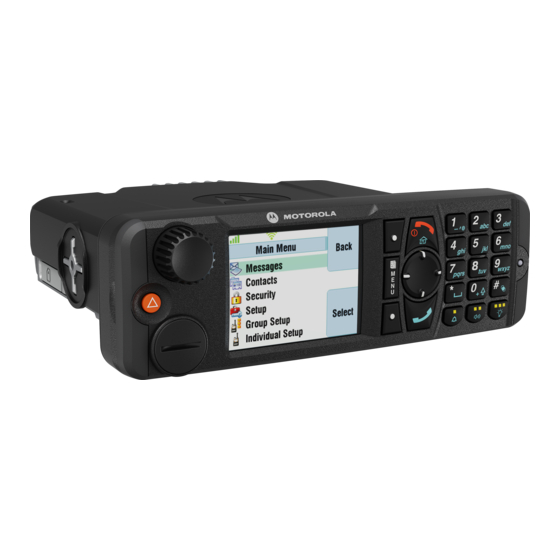
Model Descriptions
Details different radio models (M1, M2, M3, M4) and their included components.
Sales Model Nomenclature
Explains the coding system for sales model numbers and their interpretations.
Mobile Terminal Model Information
Lists model numbers, regions, and short descriptions for various terminal configurations.
Model Specifications
Provides technical specifications for the radio, including performance, dimensions, and power.
MXM600 Accessories-to-Model Chart
Maps specific antennas and cables to compatible MXM600 radio models.
Vehicle Preparation
General Guidelines for Radio Installation
Outlines general principles and considerations for installing the radio in a vehicle.
Disconnecting Your Radio Power Supply
Provides step-by-step instructions for safely disconnecting the radio's power supply.
Installing DC Power Cable
Details the procedure for installing the DC power cable, including safety precautions.
Installing Ignition Sense Cable
Explains how to install the ignition sense cable for automatic radio power control.
Radio Installation
MXM600 Dashboard Installation
Procedure for installing the MXM600 into an automotive DIN slot dashboard.
MXM600 Desktop Installation
Steps for setting up the MXM600 radio for desktop use with accessories.
MXM600 Remote Mount Installation
Guides installation of MXM600 with remote control heads and expansion heads.
Databox Expansion Head Installation
Instructions for installing the Databox Expansion Head for radio configurations.
MXM600 with IP67 Remote Control Head
Details compatibility and installation of IP67 Remote Control Heads.
Installing IP67 Remote Ethernet Control Head in a Motorcycle
Step-by-step guide for installing the IP67 RECH on a motorcycle.
Junction Box Installation
Instructions for installing the data junction box for remote and dash configurations.
Connectors and PIN Assignment
Transceiver Front – Pin Functions
Details pin assignments and functions for the transceiver front connectors.
Transceiver Rear Side
Shows the location of connectors on the rear side of the transceiver.
Accessory Connection Plan
Outlines how accessories connect to the radio's accessory connectors.
Connectors and Pin Assignment of Expansion Heads
Explains connector types and pin assignments for various expansion heads.
External Equipment Installation
Vehicle Antenna Installation
Provides guidelines for installing vehicle antennas, including site selection and safety.
Installing External Speaker
Instructions for mounting and connecting an external speaker to the radio.
Need help?
Do you have a question about the M1 and is the answer not in the manual?
Questions and answers