Table of Contents
Advertisement
Advertisement
Table of Contents

Related Manuals for Starrett HDV400


Summary of Contents for Starrett HDV400
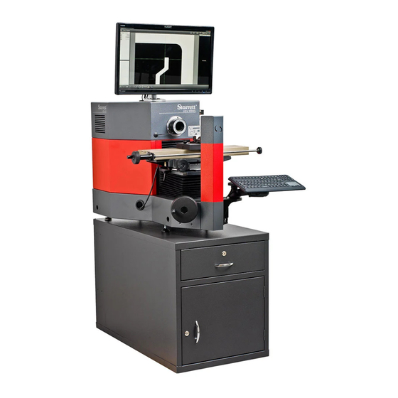
- Page 1 HDV300 & HDV400 Comparators Benchtop Horizontal Digital Video User Manual Starrett Kinemetric Engineering 26052 Merit Circle, Suite 103 Laguna Hills, CA 92653, USA www.starrettkinemetric.com Phone: (949) 348-1213 Fax: (949) 582-804 Rev. D. July 9, 2018 P/N 5930...
-
Page 2: Table Of Contents
Table of Contents 1. PREFACE ............................... 3 Welcome ............................3 Safety Symbols & Terminology....................3 Warranty ............................3 Regulatory Compliance ....................... 4 Disclaimer of Liabilities ........................ 4 Copyright & Trademark Information .................... 4 2. HDV PRODUCT LINE DESCRIPTION ....................5 Ordering Options ......................... -
Page 3: Preface
Thank you for purchasing an HDV300 or HDV400 Benchtop Horizontal Digital Video Comparator. We are pleased that your search has led you to Starrett Kinemetric Engineering, a subsidiary of the L.S. Starrett Company. This manual is intended to maximize your satisfaction with your system and ensure the best operating performance. -
Page 4: Regulatory Compliance
Safety of Machinery, Principles for Risk Assessment Disclaimer of Liabilities The L.S. Starrett Company shall have no liability or responsibility to the customer or any other person or entity with respect to any liability, loss or damage caused or alleged to be caused directly or indirectly by this documentation, or the hardware and software described in it. -
Page 5: Hdv Product Line Description
HDV PRODUCT LINE DESCRIPTION The HDV300 with 300 mm (or 12”) of travel and HDV400 with 400 mm (or 16”) of travel are hori- zontal digital video comparators which combine the best features of a vision metrology system and a horizontal optical comparator. They come with a 5-megapixel digital video camera and are available with a choice of seven telecentric lenses that provide micron-level resolution and optical distortion as low as 0.001% across the field of view (depending on the lens) for accurate field-of-... - Page 6 Feature Specification HDV300: 300 x 150 mm (12” x 6”) Measurement Range, X-Y HDV400: 400 x 150 mm (16” x 6”) (X is horizontal, Y is vertical) X-Y Motion Control Handwheels (manual models) or computer control (CNC models) 540 x 130 mm (21.3” x 5.1”) (X and Z are horizontal)
-
Page 7: Hdv System Components
HDV System Components Manual System Components LED surface illumination 24” touch-screen monitor Video camera lens LED profile System On-Off illumination switch Hand crank Two external for X-axis USB ports (left-right) Manual X-Y Protractor for stage ±15° skew measurement Right clamp for skew angle Keyboard on swing-... - Page 8 counterclockwise to release the stage, then clockwise to lock down the stage once you have set the desired skew angle. Focus adjustment over 2” (50 mm) is achieved by moving the stage horizontally toward or away from the camera optics. This adjustment uses a hand wheel with a hand crank at the front of the stage, as shown in Figure 2.
-
Page 9: Cnc System Components
Figure 3. System component overview, CNC system Manual Position and Illumination Controls in CNC System The CNC version of the HDV300 and HDV400 allows fully automatic operation under program control for illumination, for right-left position of the stage (X-axis), for up-down position of the stage (Y-axis), and for in-out position of the stage (Z-axis, used for focus adjustment). - Page 10 Position control of the stage in the X, Y and Z axes can be via the joystick and trackball unit as illustrated below. X-position control can also be via a knob at the end of the X drive shaft. First press the red emergency stop switch at the back of the joystick and trackball unit, which removes power from all servo-motors.
-
Page 11: Keyboard Adjustment
Keyboard Adjustment The system keyboard is secured magnetically to a tray, which is held by a ball joint at the end of a pivoting swing-out arm, as shown in Figure 5. Adjustment of the ball joint and pivot angle sets the keyboard angle and position. -
Page 12: Changing Lenses
Store unused lens assemblies in a safe place, since they are breakable and expensive. Lighting Control HDV300 and HDV400 system provide long-life LED lighting for surface and profile illumination. Lighting levels are adjusted via the system’s M3 software by sliding graphical controls on the touch-screen. - Page 13 If the system is to be operated under environmental conditions that are substantially different from those shown above, the system should be recalibrated under the expected conditions. Users should also consider the material characteristics of the parts under inspection, in particular coefficients of thermal expansion.
-
Page 14: 3.10 Safety Considerations
3.10 Safety Considerations General Starrett vision metrology systems are designed for safety and proper ergonomics Safety during normal use. Exercise caution when lifting, handling or moving the system to maintain equipment calibration and measurement performance. Consult Starrett if you have any question regarding transporting, using, or maintaining this system. -
Page 15: 3.11 Equipment On/Off Control
3.11 Equipment On/Off Control HDV300 and HDV400 systems have an On/Off rotary selector switch on the right side of the housing, and a rocker switch in the back just above the 115/230V power connector (as required by for CE certifica- tion). -
Page 16: Installation
Figure 9. Dimensioned outline drawing, manual system Required Tools and Equipment The following items are required to uncrate and install HDV300 or HDV400 metrology systems: 1. Forklift or pallet cart (to move shipping crate inside building), 2. Battery powered drill with Phillips bit (to remove top and sides of shipping crate), 3. -
Page 17: Uncrating The Equipment
Remove all wood screws from the side panels of the crate, then remove the panels. This will expose the HDV300 and cabinet stand (if ordered) on the pallet base of the crate. 2. Lift the cabinet stand (if ordered) off the pallet base. -
Page 18: Retainer Removal
(in the back and on the side). Starrett vision metrology systems and optical comparators are factory set for 115V or 230V AC power, depending on the destination country. Contact Starrett if you ever need to move a system to a country with different AC power. - Page 19 Training is with the new equipment and is limited to 1 to 3 people, so that these can all get hands-on time. Starrett’s objective is to create power users, who can then train other users when needed.
-
Page 20: Measurement Strategy
2.47” x 1.86” (63 x 47 mm). If the entire part cannot fit into the FOV, no problem. Simply move the stage by up to 12" (300 mm) with the HDV300 or up to 16” (400 mm) with the HDV400, and the M3 software will seamlessly integrate FOV measurements with encoder readings from stage motion. -
Page 21: M3 Software Operation
the column at the front of the instrument and is collimated so that the emitted rays are parallel to the optical axis of the imaging lens. If glare develops on edges of convoluted, reflective parts, install a furnished aperture into the back light. This aperture limits the diameter of the illuminating lens. -
Page 22: System Maintenance
SYSTEM MAINTENANCE HDV300 and HDV400 benchtop horizontal digital video comparators have been designed for years of superior service. Periodic maintenance outlined in this section should be performed to maintain the system in peak operating condition. Perform a daily inspection to ensure that the system is operating correctly and that proper safety guidelines are being followed. -
Page 23: Inline Filter Maintenance, Clean Air Kit
Figure 15. Inline Clean Air Kit Interior With the Inline Clean Air Kit, the fan on the side of the HDV300/400 is replaced with a panel and fittings to allow the use of pressurized air to keep the internals of the machine clean. Pressure between 8 and 15 psi has been found to be effective at sufficiently pressurizing the housing to prevent the ingress of dust, particulates, oil vapors, and similar such as found in machine shop environments. -
Page 24: Zoom Optics Alignment Verification
Zoom Optics Parfocality & Focus Parfocality is the condition in which the video image will remain in focus as the magnification is adjusted from highest to lowest. Starrett zoom optics are designed to maintain parfocality throughout their magnification range. To check parfocality, always reference a flat, sharp edge. Do not select a rough or sloping feature. -
Page 25: Calibration Verification
Calibration should also be verified after the system has been serviced or moved. A chrome-on-glass calibration verification standard artifact, P/N 300LSTD, is available from Starrett or its authorized distributors. This standard has a length of 300 mm and major calibration fiducials spaced every 30 mm. -
Page 26: Cleaning
3. Using the HDV system, measure the position of fiducials spaced every 30 mm. For each fiducial, take the average of multiple readings for improved accuracy. 4. Calculate the absolute measurement error for each fiducial by subtracting the calibrated position of the fiducial from the above average readings, then 5. -
Page 27: Lubrication
Use a clean soft cloth or paper towel to wipe up any excess. NOTE: Use only approved lubricants, as inappropriate lubricants can damage system components. Approved lubricants may be obtained by contacting Starrett or an authorized Starrett representative. -
Page 28: Glossary
Axis A direction which allows movement and along which dimensions can be measured. In the HDV300, the X-axis is horizontal from left to right, and the Y axis is vertical from bottom to top. Blooming A condition where the parts of the video image are distorted by oversa- turated bright regions, making objects appear larger than they really are. - Page 29 Repeatability The three-sigma variation of multiple readings on the same object that is positioned at multiple locations across the field of view. Resolution The least significant digit to which a physical quantity can be read. High resolution does not imply high accuracy. Squareness The alignment of the camera relative to the motion of the metrology stage.
Need help?
Do you have a question about the HDV400 and is the answer not in the manual?
Questions and answers