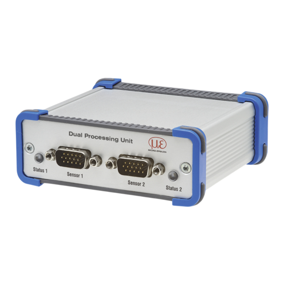
Summarization of Contents
Safety
Symbols and Warnings
Explains symbols and provides crucial safety warnings for operation and power supply.
Functional Principle and Technical Data
Technical Data
Lists detailed specifications, including supply voltage, interfaces, and compatibility.
Installation and Assembly
Electrical Connections and LEDs
Explains pin assignments and LED indicators for system status and connections.
Laser Operation
Switching the Laser On/Off
Details the procedure for switching the sensor's measuring laser on and off.
Operation Setup
USB Driver Installation
Guides users through the process of installing the necessary USB driver for PC connection.
Ethernet Control
Ethernet Requirements
Outlines requirements for Ethernet connection and direct PC linking.
Web Interface Access
Accessing the Web Interface
Details how to launch and navigate the controller's web interface.
Measurement Display
Web Browser Measurement Display
Explains how to display and interpret measurement values using the web interface.
Advanced Operation
ASCII Command Programming
Details how to configure the controller using ASCII commands via RS422 or Ethernet.
Controller Parameter Settings
Channel Settings Overview
Covers configuration for sensor or encoder inputs on channels 1 and 2.
Data Recording Configuration
Measurement Task and Rate
Configures measurement tasks, measuring rates, and error handling settings.
Processing Options
Filter and Averaging
Explains the different filter algorithms and averaging techniques available.
Data Output Control
Trigger and Synchronization
Configures triggers for data output and synchronization methods between sensors.
USB Data and Ethernet Settings
Ethernet Settings Configuration
Configures IP address, subnet mask, gateway, and transmission type for Ethernet.
Output Settings
Digital Outputs Configuration
Configures digital outputs for error signals and limit values.
System Settings
Language and Unit Settings
Configures the language and units displayed on the web interface.
Settings Management
Saving and Loading Settings
Details procedures for saving current configurations and loading them later.
ASCII Communication
General Communication Principles
Basic principles of ASCII command structure, parameters, and error reporting.
General Commands
Controller Information Retrieval
Details commands for retrieving controller information and sensor status.
Triggering and Data Output Interfaces
Triggering Modes and Levels
Configures trigger modes, levels, and counts for data acquisition.
Measurement Configuration
Measurement Modes and Rates
Configuration of measurement modes, rates, averaging, and mastering for sensors.
Data Output Control
Digital Output Selection
Configuration of digital outputs for measurement values and status signals.
Scaling and Error Handling
Output Value Scaling
Sets scaling for DPU values, defining output range based on minimum and maximum values.
Encoder Settings
Encoder Interpolation and Reference
Configures encoder interpolation mode and the effect of the reference track.
Encoder as Trigger
Trigger Values and Steps
Sets parameters for using encoder signals as triggers, including min/max values and steps.


Need help?
Do you have a question about the ILD1900 and is the answer not in the manual?
Questions and answers