Table of Contents
Advertisement
Quick Links
Advertisement
Table of Contents

Related Manuals for MICRO-EPSILON IF2030/PNET


Summary of Contents for MICRO-EPSILON IF2030/PNET
- Page 1 Operating Instructions IF2030/PNET...
- Page 2 Interface Module MICRO-EPSILON MESSTECHNIK GmbH & Co. KG Königbacher Straße 15 D-94496 Ortenburg/Germany Tel. +49 (0) 8542/168-0 Fax +49 (0) 8542/168-90 email info@micro-epsilon.de www.micro-epsilon.com...
-
Page 3: Table Of Contents
Option 2: TIA Components ......................17 5.2.3 Option 3: Directly Access the Object Directory ................17 Data Format ..............................18 Object Directory ............................. 19 Sequence When Writing and Reading Acyclical Data .................. 26 Sequence When Writing Structured Data ..................... 29 IF2030/PNET... - Page 4 A 4.4 INC5701 ................................. 48 A 4.5 ACS7000 ................................ 50 A 4.6 IFC2421, IFC2422, IFC2451, IFC2461, IFC2471 ................... 52 A 4.7 ILD1320, ILD1420 ............................53 A 4.8 ILD1750 ................................54 A 4.9 ILD2300 ................................55 A 4.10 ODC2520 ............................... 56 IF2030/PNET...
-
Page 5: Safety
> Damage to or destruction of the interface module The supply voltage must not exceed the specified limits. > Damage to or destruction of the interface module Avoid shocks and impacts to the interface module. > Damage to or destruction of the interface module IF2030/PNET Page 5... -
Page 6: Notes On Ce Marking
- The IF2030/PNET must only be operated within the limits specified in the technical data; see Chap. 2.2. - The IF2030/PNET must be used in such a way that no persons are endangered or machines and other material goods are damaged in the event of malfunction or total failure. -
Page 7: Functional Principle, Technical Data
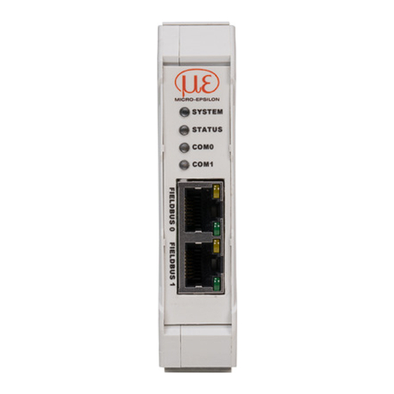
Functional Principle, Technical Data Functional Principle, Technical Data Functional Principle The IF2030/PNET interface module is used to convert the internal Micro-Epsilon sensor protocol (RS485 or RS422) to Profinet IO. Features: - Synchronization output, LED status display - Profinet interface - Housing for top-hat rail... - Page 8 -8 ... +13 V, ESD 15 kV Terminating resistor 120 Ohm, integrated Supported sensors, controller ACS7000 IFC24x1, IFC242x ILD1320, ILD1420, ILD1750, ILD2300 ODC2520 Synchronization output Level TTL or HTL (Profinet IRT only) No overvoltage protection LED status display System, status, COM0, COM1 IF2030/PNET Page 8...
-
Page 9: Delivery
After unpacking, check immediately for completeness and transport damage. If there is damage or parts are missing, immediately contact the manufacturer or supplier. Download GSDML file, available at https://www.micro-epsilon.de/service/download/ TIA function components for easier configuration, available at https://www.micro-epsilon.de/ser- vice/download/ Storage Storage temperature: -20 to +70 °C (-4 to +158 °F) -
Page 10: Installation And Assembly
Installation and Assembly Installation and Assembly Ensure careful handling during installation and operation. Installation of the Interface Module +0.35 +0.6 22.6 -0.3 -0.4 (.89) (4.21) TS35 Top-hat rail 113.7 (4.48) Fig. 1 IF2030/PNET dimensional drawing, dimensions in mm IF2030/PNET Page 10... -
Page 11: Pin Assignment
Terminal 1 Terminal 3 shield connection Fig. 2 Interface module terminals 1) Internally connected to supply ground 2) If the distance between IF2030/PNET and the sensor/controller is long, a separate supply for the sensor/controller may be advisable. IF2030/PNET Page 11... -
Page 12: Supply Voltage
1 to a voltage supply. Maximum cable length 3 m. The voltage supply must match that of the connected sensor, because the voltage is internally daisy-chained. MICRO-EPSILON recommends using the optionally available power supply PS2020, input 100 - 240 VAC, output 24 VDC/2.5 A, see appendix. -
Page 13: Connection Options
ODC2520 Fig. 5 Connection examples for IF2030/PNET The length of the cable between IF2030/PNET and sensor/controller is 10 m at most. Because of the PCx/8-M12 cable, the sensor supply for ACC5703 and INC5701 sensors is possible only via the IF2030/PNET. -
Page 14: Cable Termination At Interface
We recommend a 120 Ohm terminating resistor between the signal lines at both the bus start and end. IF2030/PNET works as a master for both interfaces; internally, a 120 Ohm terminating resistor has already been permanently incorporated. The IF2030/PNET should be at the bus start. -
Page 15: Fieldbus Cabling
(MRP = Media Redundancy Protocol) between the output port of the last slave device and channel 1 of the IO controller. IF2030 can participate in an MRP ring as a client; however, it cannot manage the ring. To achieve ring functionality, all participants must be configured as ring participants. IF2030/PNET Page 15... -
Page 16: Commissioning
Please refer to the operating instructions of the corresponding sensor for detailed information on config- uring the sensor. Baud Rate and Sensor Interface IF2030/PNET must be set for the interface used and the sensor’s baud rate. The baud rate and sensor interface can be configured in various ways. Sensor/Controller Baudrate [Baud] RS485 RS422... -
Page 17: Option 2: Tia Components
5.2.2 Option 2: TIA Components The download package with the GSDML file includes preset function components that allow for easy access to options for the IF2030/PNET. Select the IF2030_BaudrateInterface component and transfer the parameters, see Chap. 5.7.3. 5.2.3 Option 3: Directly Access the Object Directory Use the WRREC_DB function component to send the desired baud rate and sensor interface to the IF2030/PNET, see Chap. -
Page 18: Data Format
00000001 0xA3 M-Byte 01001100 Value 1: 001010 001100 000001 0x00 H-Byte 11001010 0x00 0x2A L-Byte 00101010 0xF0 Value 2: 111111 000000 101010 M-Byte 01000000 0x03 H-Byte 10111111 0x00 Fig. 11 Interpretation of RS422 sensor data in IF2030/PNET IF2030/PNET Page 18... -
Page 19: Object Directory
0: Disable HTTL synchronization 0x2027 0 Uint8 HTTL Sync 1: Enable HTTL synchronization enable/disable cyclic 0: Disable 8 byte status header in cyclic data 0x2028 0 Uint8 status header 1: Enable 8 byte status header in cyclic data IF2030/PNET Page 19... - Page 20 Test software version Uint8 Test hour Uint8 Test day Uint8 Test month Uint8 Test year Int32 Article number circuit board Int32 Serial number circuit board Uint8[32] Name Uint8 sensor/channel count Uint8 protocol block count Uint8[164] R protocol blocks IF2030/PNET Page 20...
- Page 21 RS485 bus diagnostic block (if available) Uint8 NrOfObjects Specifying an index lets you scroll through exist- Uint8 RW page index to read ing pages Uint8 number of pages Uint8 diagnose Type Uint8[235] R String Page Diagnostic message IF2030/PNET Page 21...
- Page 22 Float Nominal offset Nominal offset Float current measuring range Actual measuring range Float current offset Actual offset Uint8[32] Target material Target material Uint8[32] Sensor/channel name Sensor/channel name uint8 extension length Length of block extension uint8[138] R extension IF2030/PNET Page 22...
- Page 23 NrOfObjects Please refer to the sensor documentation for avai- Uint16 RW Parameter ID lable parameter IDs and their types Uint8 RW Reserved Float RW Value Value Uint8[14] Name Designation Uint8[8] Unit Unit as a string Float Float IF2030/PNET Page 23...
- Page 24 NrOfObjects Please refer to the sensor documentation for avai- Uint16 RW Parameter ID lable parameter IDs and their types Uint8 RW Reserved Uint32 RW Value Value Uint8[14] Name Designation Uint8[8] Unit Unit as a string Uint32 Uint32 IF2030/PNET Page 24...
- Page 25 Buffer for a 128-character ASCII command, termi- Uint8[128] RW Send Cmd nation with ‘\n’ or 0x0A Answer from sensor without shortening, e.g., Line Uint8[896] R Cmd Answer feed; if buffer overflows, e.g., PRINT ALL, answer is truncated IF2030/PNET Page 25...
-
Page 26: Sequence When Writing And Reading Acyclical Data
'L' 'A' 'S' 'E' 'R' 'P' 'O' 'W' 0x20 'O' 0x0A DONE => BUSY => Status/Result Output ERROR => STATUS => Fig. 12 SPS write command with 8 Byte prefix to turn on the laser light source on the sensor IF2030/PNET Page 26... - Page 27 Objekt Index LEN := Data Length 'L' 'A' 'S' 'E' 'R' 'P' 'O' 'W' 0x20 'O' 'N' 0x0A RECORD => VALID => BUSY => ERROR => Status/Result Output STATUS => LEN => Fig. 13 SPS read command IF2030/PNET Page 27...
- Page 28 'L' 'A' 'S' 'E' 'R' 'P' 'O' 'W' 0x20 'O' 'F' 'F' 0x0A RECORD => VALID => BUSY => ERROR => Status/Result Output STATUS => LEN => Fig. 15 SPS read command to turn off the laser light source on the sensor IF2030/PNET Page 28...
-
Page 29: Sequence When Writing Structured Data
RECORD := 0 0 0x01 0 0x07 0 0 0 0xF8 0x02 0x00 0xE7 0x03 0x00 0x00 DONE => BUSY => Status/Result Output ERROR => STATUS => Fig. 16 Write command with data from SPS to IF2030/PNET IF2030/PNET Page 29... -
Page 30: Tia Function Components
5.7.1 General You can configure your IF2030/PNET via S7 by using several function components. They cover core functions that can be used for all compatible Micro-Epsilon sensors. The components are available in an unencrypted form to allow you to view the code (“Structured Control Language”) and use it as a template for your own programs. -
Page 31: Importing Function Components
Open the context menu by right-clicking the file and select the Generate blocks from source function in that menu. If displayed, confirm a message that existing blocks will be overwritten. IF2030/PNET Page 31... - Page 32 Program compo- nents folder. You can also view the re- sult of generating them in the Inspec- tion window on the Info > Compile tab. Please note that these messages refer to the source file. IF2030/PNET Page 32...
-
Page 33: Executing Function Component
Now create the necessary variables, depending on the function component. The starting value is the value used when the data component is loaded into the CPU’s memory. Next, click the Save project button (top left on the function bar). IF2030/PNET Page 33... - Page 34 Open the Main [OB1] organization component by double-clicking it. Mark your function component and drag it into the pro- gram of the previously opened organization component. There is no requirement that the call be performed via the main program OB1; that program is always processed by the CPU by default. IF2030/PNET Page 34...
- Page 35 The components that were translated successfully are then displayed under Inspection window > Info > Translation. After successful translation, the entire control system with the program generated, including the hardware configuration, can be load- ed by using the Load to device symbol button. IF2030/PNET Page 35...
-
Page 36: Basic Settings Module
5.7.4 Basic Settings Module You can specify basic settings using the TIA portal inter- face. Proceed as follows to configure the IF2030/PNET based on a few basic parameters. In the Hardware catalog, select the Basic settings output module and place it in the next free slot in the Device overview. - Page 37 Reboot the IF2030/PNET to have the changes take effect! This step is necessary because of the selected/used mechanism for establishing a GUI to parameterize the IF2030/PNET; it pre- vents the configuration from being sent repeatedly to the CPU as programs are run.
-
Page 38: Liability For Material Defects
The liability for material defects is 12 months from delivery. Within this period, defective parts, except for wearing parts, will be repaired or replaced free of charge, if the device is returned to MICRO-EPSILON with shipping costs prepaid. Any damage that is caused by improper handling, the use of force or by repairs or modifications by third parties is not covered by the liability for material defects. -
Page 39: Appendix
2.5 A, input 100 - 240 VAC, output 24 VDC/2.5 A, installation type; installation on symmetrical standard rail 35 mm x 7.5 mm, DIN 50022 Factory Settings Baudrate 9600 Baud cycleMinTime 0 (= IF2030 calculates cycle time) SensorInterface MEO+RS422 HTTL CyclicDebugHeader IF2030/PNET Page 39... -
Page 40: A 3 Integration Into Tia Portal
Import the GSDML file. To do so, in the Extras > Manage device description files (DDF) menu, select the path for the file <GSDML-Vx-MICRO-EPSILON-IF2030.xml>. Click the Install button. Fig. 18 Importing the device description file After installation, switch to the project view. - Page 41 > PROFINET IO > I/O > MICRO-EPSILON MESSTECHNIK GmbH > PNS > IF2030/ PNET. Connect the green PN port in the device diagram to the PN network or to the PN connection of the SPS. Fig. 19 Selecting IF2030/PNET as the hardware IF2030/PNET Page 41...
- Page 42 Enter the device name for identification in the PN network. Switch to the Device view, dou- ble-click your IF2030/PNET and set its device name in the Inspection win- dow (Properties > General tab). The device name is used to identify the device on the PN network and as an address;...
- Page 43 In the open dialog window, click the Update list button. Potential devices on the PN network are displayed. In the list that is now displayed, mark the row with your IF2030/PNET that is to be renamed; field Status, “Device name is differ- ent”. Finally, click the Assign name button.
- Page 44 TIA); drag it to the first free slot in the Device overview. In the hardware catalog, select the output mod- ule Basic settings and drag it to the next free slot in the device overview. IF2030/PNET Page 44...
-
Page 45: A 4 Sensor Values, Data Format, Conversion
The sensors or controllers do not solely output distance values. The overview below describes the conversion during output of dis- tance values. Please refer to the corresponding operating instructions for detailed information on conversion when additional values are output. IF2030/PNET Page 45... -
Page 46: Acc5703
Measuring value 1 z-axis [bit 8:15] manuals/man--inerti- Float 32 bit Data[n+m+2] Measuring value 1 z-axis [bit 16:23] alSENSOR-ACC5703- Data[n+m+2] Measuring value 1 z-axis [bit 24:31] -en.pdf Fig. 21 Encoding of Measured Data in the Transmission Protocol, ACC5703 IF2030/PNET Page 46... -
Page 47: A 4.3 Dt6120
Measuring value m [31:24] measurements are output. Fig. 22 Encoding of Measured Data in the Transmission Protocol, DT6120 Please refer to the operating instructions for the capacitive displacement measuring system for more information. The current version is available at: https://www.micro-epsilon.de/download/manuals/man--capaNCDT-6110-6120IP--en.pdf IF2030/PNET Page 47... -
Page 48: A 4.4 Inc5701
Measured value 2 [bit 0:7] Float 32 bit Data[13] Measured value 2 [bit 8:15] Data[14] Measured value 2 [bit 16:23] Data[15] Measured value 2 [bit 24:31] Fig. 23 Encoding of Measured Data in the Transmission Protocol, INC5701S IF2030/PNET Page 48... - Page 49 Measuring value 2 SF [bit 24:31] Data[n + 5] Measuring value 2 SF [bit 24:31] Fig. 24 Encoding of Measured Data in the Transmission Protocol, INC5701D 1) LP = Low pass filter 2) SF = SensorFUSION filter IF2030/PNET Page 49...
-
Page 50: A 4.5 Acs7000
Measuring rate 250 Hz ex factory, all color values and color distances. Up to 32 output values can be transmitted at the same time. Baud rate 115200 b/s ACS7000 supplies 3 bytes per value at the output. These bytes are coded by the IF2030/PNET into 4 bytes, see Chap. 5.3. Scaled Group Name... - Page 51 MinDistID Fig. 25 Overview of output data via RS422 Please refer to the operating instructions for the color measuring system colorCONTROL ACS7000 for more information, especially about possible output values. The current version is available at: https://www.micro-epsilon.com/download/manuals/man--colorCONTROL-ACS7000--en.pdf IF2030/PNET Page 51...
-
Page 52: A 4.6 Ifc2421, Ifc2422, Ifc2451, Ifc2461
IFC24xx supplies 3 bytes per value at the output. These bytes are coded by the IF2030/PNET into 4 bytes, see Chap. 5.3. The linearized measuring values can be converted in µm using the following formula:... -
Page 53: Ild1320, Ild1420
The digital measurements are output at the sensor as unsigned digital values (raw values). The sensors supply 3 bytes per value at the output. These bytes are coded by the IF2030/PNET into 4 bytes, see Chap. 5.3. The linearized measuring values can be converted in µm using the following formula:... -
Page 54: Ild1750
The digital measurements are output at the sensor as unsigned digital values (raw values). The sensors supply 3 bytes per value at the output. These bytes are coded by the IF2030/PNET into 4 bytes, see Chap. 5.3. The linearized measuring values can be converted in µm using the following formula:... -
Page 55: Ild2300
The digital measurements are output at the sensor as unsigned digital values (raw values). 16 Bit per value are transmitted. The sen- sors supply 3 bytes per value at the output. These bytes are coded by the IF2030/PNET into 4 bytes, see Chap. 5.3. -
Page 56: A 4.10 Odc2520
RS422 interface. The ODC2520 supplies 3 bytes per value at the output. These bytes are coded by the IF2030/PNET into 4 bytes, see Chap. 5.3. The linearized measuring values can be converted in µm using the following formula: x = Measuring value (edge position, difference, center axis) in μm... - Page 58 MICRO-EPSILON MESSTECHNIK GmbH & Co. KG X9751394-A021089MSC Königbacher Str. 15 · 94496 Ortenburg/Germany MICRO-EPSILON MESSTECHNIK Tel. +49 (0) 8542/168-0 · Fax +49 (0) 8542/168-90 *X9751394-A02* info@micro-epsilon.de · www.micro-epsilon.de...
Need help?
Do you have a question about the IF2030/PNET and is the answer not in the manual?
Questions and answers