Sign In
Upload
Download
Table of Contents
Contents
Add to my manuals
Delete from my manuals
Share
URL of this page:
HTML Link:
Bookmark this page
Add
Manual will be automatically added to "My Manuals"
Print this page
×
Bookmark added
×
Added to my manuals
Manuals
Brands
MICRO-EPSILON Manuals
Recording Equipment
ILD1 20 Series
Operating instructions manual
MICRO-EPSILON ILD1 20 Series Operating Instructions Manual
Dual processing unit
Hide thumbs
1
2
Table Of Contents
3
4
5
6
7
8
9
10
11
12
13
14
15
16
17
18
19
20
21
22
23
24
25
26
27
28
29
30
31
32
33
34
35
36
37
38
39
40
41
42
43
44
45
46
47
48
49
50
51
52
53
54
55
56
57
58
59
60
page
of
60
Go
/
60
Contents
Table of Contents
Bookmarks
Table of Contents
Table of Contents
Safety
Symbols Used
Warnings
Notes on Product Marking
CE Marking
UKCA Marking
Intended Use
Proper Environment
Functional Principle, Technical Data
Functional Principle
Technical Data
Delivery
Unpacking, Included in Delivery
Storage
Installation and Assembly
Assembling the Controller
Electrical Connections, Leds
Switching on the Laser
Operation
Getting Ready for Operation
Installing the USB Driver
Select Properties
Software Update
Control Via Ethernet
Requirements
Direct Link to PC
Access Via Ethernet
Measurement Value Display with Web Browser
Programming Via ASCII Commands
Time Response, Measurement Value Flow
Setting Controller Parameters
Preparations for the Setting Options
Overview of Parameters
Channel Settings
Channel Type
Channel 1, Channel 2 - Sensor
Channel 1, Channel 2 - Encoder
Digital Input
Data Recording
Measurement Task
Measuring Rate
Error Handling
Processing
Filter/Averaging
Mastering / Zeroing
Two-Point Mastering
Data Output Trigger
Synchronization
Output Data Rate
Outputs
Digital Interface Selection
Ethernet Data Selection
USB Data Selection
Ethernet Settings
USB Settings
Digital Outputs
Analog Output 1, Analog Output 2
System Settings
Language & Unit
Saving Settings
Loading Settings
Managing Settings
Resetting
Software Support with Medaqlib
Disclaimer
Decommissioning, Disposal
Service, Repair
Service & Repair
Optional Accessories
ASCII Communication
General
Data Protocol
General Commands
Calling up Controller Information
Searching for a Sensor
Calling up Sensor Information
Reading out All Settings
Language Settings
Synchronization
Booting the Controller
Sending a Command to the Sensor
Triggering
Trigger Mode
Trigger Level
Number of Measurement Values to be Output
Software Trigger
Data Output Via Digital Interfaces
Ethernet Settings
Setting for Ethernet Measurement Value Transmission
Parameter Management, Load/Save Settings
Saving Parameters
Loading Parameters
Reset Factory Settings
Resetting the Statistics
Measurement
Selection of Measuring Mode
Setting the Measuring Rate
Outputting Temperature Signals
Sensor Measurement Value Averaging
Mastering / Zeroing
Two-Point Mastering
Switch of Measurement Value Display
Switching the Laser on / off
Data Output
Selection of Digital Output
Selection of Interface for Reduced Data Output
Scaling Output Values
Error Handling
Data Selection for USB
Data Selection for Ethernet
Information about Signals Set
Function Selection MFI Input
Digital Error Outputs
Limit Value Testing
Analog Output
Selection of the Output Range for the Analog Output
Scaling the Analog Output
Encoder Settings
General
Encoder Interpolation Mode
Encoder Reference Track
Encoder Start Value
Loading the Encoder Start Value
Encoder Counting Direction
Resetting the Reference Marks
Resetting the Encoder
Querying the Encoder Value
Querying the Reference Counter
Encoder Acquisition Source
Encoder as Trigger
Number of Triggers
Minimum Trigger Value
Maximum Trigger Value
Trigger Start Value
Trigger Pulse Width
Index
Advertisement
Quick Links
Download this manual
ILD1x20
ODC2520
ILD1750
ILD1900
ILD2300
IFC24xx
(current models in the catalog)
Operating Instructions
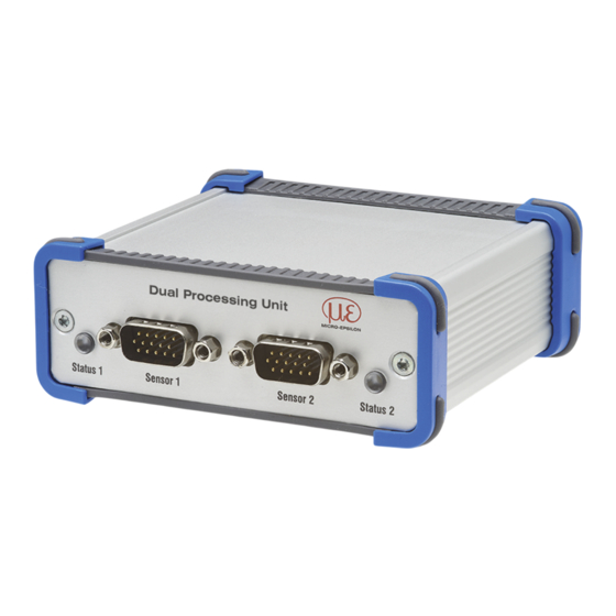
Dual Processing Unit
Table of
Contents
Previous
Page
Next
Page
1
2
3
4
5
Advertisement
Table of Contents
Need help?
Do you have a question about the ILD1 20 Series and is the answer not in the manual?
Ask a question
Questions and answers
Related Manuals for MICRO-EPSILON ILD1 20 Series
Recording Equipment MICRO-EPSILON IF2030/PNET Operating Instructions Manual
(58 pages)
Recording Equipment MICRO-EPSILON IF2035 Assembly Instructions
(2 pages)
Recording Equipment MICRO-EPSILON IF2035-PROFINET Assembly Instructions
(2 pages)
Recording Equipment MICRO-EPSILON ILD1750 Operating Instructions Manual
Dual processing unit (60 pages)
Recording Equipment MICRO-EPSILON ILD1900 Operating Instructions Manual
Dual processing unit (60 pages)
Recording Equipment MICRO-EPSILON ILD2300 Operating Instructions Manual
Dual processing unit (60 pages)
This manual is also suitable for:
Ild1750
Ild1900
Ild2300
Odc2520
Table of Contents
Print
Rename the bookmark
Delete bookmark?
Delete from my manuals?
Login
Sign In
OR
Sign in with Facebook
Sign in with Google
Upload manual
Upload from disk
Upload from URL


Need help?
Do you have a question about the ILD1 20 Series and is the answer not in the manual?
Questions and answers