
Related Manuals for IBM MTM 2076-AF6


Summarization of Contents
Safety and Environmental Notices
Safety Notices and Labels
Guidance on reviewing safety notices and information labels before product use.
Caution Notices for the System
Ensuring understanding of system caution notices and referencing translated notices.
Danger Notices for the System
Familiarizing with system danger notices and finding translated versions.
Special Caution and Safety Notices
Addressing specific safety issues relevant to the provided equipment.
General Safety
Following general safety guidelines when servicing the Storwize V7000.
Handling Static-Sensitive Devices
Understanding and following procedures for handling static-sensitive devices.
Environmental Notices
Information on environmental notices for IBM Systems products.
About This Guide
Who Should Use This Guide
Identifying the intended audience for the installation guide.
Publications and Related Libraries
Locating product manuals, other publications, and websites for system information.
Related Websites
Listing websites that provide information about the system and related products.
Sending Your Comments
Providing feedback on the documentation for accuracy and quality.
How to Get Information, Help, and Technical Assistance
Help and Service
Guidelines and contact information for obtaining customer support and service.
Software Option
Information required when calling for software-related support assistance.
Hardware Option
Information required when calling for hardware-related support assistance.
Chapter 1. Before You Begin the Installation
Reviewing Your Packing Slip
Verifying shipment contents against the packing slip to ensure all items are included.
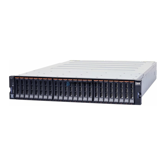
Identify the Hardware Components
Identifying hardware components and port locations for control and expansion enclosures.
Identifying Storwize V7000 2076-624 and Storwize V7000 2076-U7A Node Canisters
Distinguishing between different Storwize V7000 node canister models based on hardware changes.
Verify Environmental Requirements
Ensuring physical site meets environmental and electrical requirements for reliable system operation.
Review Enclosure Location Guidelines
Familiarizing with guidelines for proper placement of enclosures within the rack.
Chapter 2. Installing the System Hardware
Installing Support Rails for the Storwize V7000 Gen2 and Storwize V7000 Gen2+ Control Enclosure
Procedure for installing support rails for control enclosures in a rack.
Installing Support Rails for 2U Expansion Enclosures
Procedure for installing support rails for 2U expansion enclosures in a rack.
Installing a Storwize V7000 Gen2 and Storwize V7000 Gen2+ Control Enclosure
Step-by-step guide for installing control enclosures into the rack.
Connecting Storwize V7000 Gen2 and Expansion Enclosures to the Control Enclosure
Connecting expansion enclosures to the control enclosure using SAS cables.
SAS Cabling Guidelines
Guidelines for correctly orienting and connecting SAS cables between enclosures.
Removing the Top Cover: 2076-92F
Procedure for removing the top cover of the 2076-92F expansion enclosure for service.
Installing or Replacing the Support Rails: 2076-92F
Steps for installing or replacing support rails for the 2076-92F expansion enclosure.
Installing or Replacing an Expansion Enclosure in a Rack: 2076-92F
Procedure for installing or reinstalling the 2076-92F expansion enclosure in a rack.
Installing or Replacing an Expansion Canister: 2076-92F
Procedure for installing or replacing an expansion canister in the 2076-92F expansion enclosure.
Removing or Moving the Cable-Management Arm: 2076-92F
Steps to remove or move the cable management arm for service tasks.
Installing or Replacing the Cable-Management Arm: 2076-92F
Procedure for installing or replacing the cable management arm assembly.
Installing or Replacing the Top Cover: 2076-92F
Procedure for installing or replacing the top cover of the 2076-92F expansion enclosure.
Installing or Replacing a Drive: 2076-92F
Procedure for installing or replacing a drive in the 2076-92F expansion enclosure.
Installing or Replacing a Secondary Expander Module: 2076-92F
Procedure for installing or replacing a secondary expander module in the 2076-92F expansion enclosure.
Installing or Replacing the Fascia: 2076-92F
Procedure for installing or replacing fascia components on the front of the enclosure.
Installing or Replacing a Power Supply: 2076-92F
Procedure for replacing power supply units in the 2076-92F expansion enclosure.
Removing the Fascia: 2076-92F
Procedure for removing fascia components from the front of the 2076-92F expansion enclosure.
Removing and Installing a SAS Cable: 2076-92F
Procedures for attaching, removing, and installing SAS cables.
Installing or Replacing a Fan Module: 2076-92F
Procedure for installing or replacing a fan module in the 2076-92F expansion enclosure.
Installing or Replacing a Fan Interface Board: 2076-92F
Procedure for installing or replacing a fan interface board (FIB).
Removing an Expansion Enclosure from a Rack: 2076-92F
Procedure for sliding or completely removing the 2076-92F expansion enclosure from the rack.
Removing a Power Supply: 2076-92F
Procedure for removing a power supply unit (PSU) from the 2076-92F expansion enclosure.
Removing a Drive: 2076-92F
Procedure for removing a drive from the 2076-92F expansion enclosure.
Removing a Secondary Expander Module: 2076-92F
Procedure for removing a secondary expander module from the 2076-92F expansion enclosure.
Removing an Expansion Canister: 2076-92F
Procedure for removing an expansion canister from the 2076-92F expansion enclosure.
Removing a Fan Module: 2076-92F
Procedure for removing a fan module from the 2076-92F expansion enclosure.
Removing a Fan Interface Board: 2076-92F
Procedure for removing a fan interface board (FIB) from the 2076-92F expansion enclosure.
Replacing an Enclosure: 2076-92F
Procedure for replacing a faulty enclosure with a new one from FRU stock.
Removing the Display Panel Assembly: 2076-92F
Procedure for removing the display panel assembly from the 2076-92F expansion enclosure.
Installing or Replacing the Display Panel Assembly: 2076-92F
Procedure for installing or replacing the display panel assembly.
Removing the Support Rails: 2076-92F
Procedure for removing the support rails from the 2076-92F expansion enclosure.
Connecting Optional SAS Expansion Enclosures: 2076-92F
Connecting optional 5U expansion enclosures to the system using SAS cables.
Powering Off the Expansion Enclosure: 2076-92F
Procedure for safely powering down the 2076-92F expansion enclosure.
Chapter 3. Configuring the System
Checking Your Web Browser Settings for the Management GUI
Ensuring web browser compatibility and settings for accessing the management GUI.
User Name and Password for System Initialization
Listing the default credentials for system initialization GUI access.
Initializing the System by Using the Technician Port
Procedure for initializing a new system using a PC connected to the technician port.
Adding an Expansion Enclosure to an Existing System
Steps to add an expansion enclosure to an already configured system via the management GUI.
Adding a Control Enclosure to an Existing System
Steps to add a control enclosure to an existing system, including SAN zoning.
Appendix A. Accessibility Features for the System
Accessibility Features
Overview of major accessibility features for the system, including screen reader support.
Keyboard Navigation
Using keys or key combinations for operations and menu actions without a mouse.
IBM and Accessibility
Information about IBM's commitment to accessibility and resources for further details.
Appendix B. Where to Find the Statement of Limited Warranty
Statement of Limited Warranty
Information on how to access the Statement of Limited Warranty in hardcopy and online.
Notices
Trademarks
List of IBM and other company trademarks mentioned in the document.
Homologation Statement
Statement regarding product certification for connection to public telecommunication networks.
Electromagnetic Compatibility Notices
Statements regarding electromagnetic compatibility (EMC) compliance.
Canada Notice
EMC compliance notice specific to Canada.
European Community and Morocco Notice
EMC compliance notice for the European Community and Morocco.
Germany Notice
EMC compliance notice specific to Germany, including warnings for Class A devices.
Japan Electronics and Information Technology Industries Association (JEITA) Notice
JEITA notices related to product specifications and compliance.
Japan Voluntary Control Council for Interference (VCCI) Notice
VCCI notice regarding interference control for electronic devices.
Korea Notice
Notice regarding product compliance in Korea.
People's Republic of China Notice
Notice regarding product compliance in the People's Republic of China.
Russia Notice
Notice regarding product compliance in Russia.
Taiwan Notice
IBM Taiwan contact information and notices.
United States Federal Communications Commission (FCC) Notice
FCC compliance statement for Class A digital devices.
Need help?
Do you have a question about the MTM 2076-AF6 and is the answer not in the manual?
Questions and answers