
Related Manuals for Sinclair S-THERM GSH-160ERB


Summary of Contents for Sinclair S-THERM GSH-160ERB
- Page 1 SERVICE MANUAL 02 | 17 -08 -2022 S-THERM ONTARIO ALL-IN -ONE SERIES AIR TO WATER HEAT PUM PS GSH-XXXTRB + GSH-XXXERB GSH-XXXTRB2 + GSH-XXXERB GSH-XXXTRB2 + GSH-XXXERB2 GSH-XXXTRB2-3 + GSH-XXXERB-3...
- Page 2 IMPORT ANT NOTE: Read this manual carefully before installing or operating your new heat pump. Make sure to save this manual for future reference.
-
Page 3: Table Of Contents
Table of Contents SPECIFICATIONS ....................... 1 1 Product Data ..............................1 1.1 Models ..............................1 1.2 Product Features ............................3 1.3 Operating Principle ..........................6 1.4 Specifications ............................7 2 Exploded Views and Parts List........................33 3 Scope of Delivery ............................55 CONTROL ......................... 56 1 Concept of Integral Control ........................ - Page 4 2.11 Wiring of the Additional Heat Source ....................124 2.12 Wiring of the Access Card Reader (Gate-controller) ..............125 2.13 Wiring of the External Air Temperature Sensor (Remote Temperature Sensor) ......126 2.14 Wiring of the Thermostat ......................... 127 2.15 Wiring of the Controller ........................128 3 Commissioning and Trial Run .........................
-
Page 5: Specifications
Specifications 1 Product Data 1.1 Models 1.1.1 Outdoor Unit Cooling Heating Power Series Model capacity capacity Refrigerant Appearance supply (kW) (kW) GSH-40ERB GSH-60ERB GSH-40ERB2 GSH-60ERB2 GSH-80ERB GSH-100ERB GSH-80ERB2 GSH-100ERB2 9.35 GSH-80ERB-3 GSH-100ERB-3 GSH-120ERB GSH-140ERB 12.6 GSH-160ERB 15.5 GSH-120ERB-3 GSH-140ERB-3 12.6 GSH-160ERB-3 15.5 CAUTION! For some units, the “COMMISSIONING”... - Page 6 1.1.2 Indoor Unit Power Series Model Appearance supply GSH-40TRB GSH-60TRB GSH-80TRB GSH-100TRB GSH-40TRB2 GSH-60TRB2 GSH-80TRB2 GSH-100TRB2 GSH-120TRB2 GSH-140TRB2 GSH-160TRB2 GSH-80TRB2-3 GSH-100TRB2-3 GSH-120TRB2-3 GSH-140TRB2-3 GSH-160TRB2-3 1.1.3 Possible Combinations of the Outdoor and Indoor Units Heating spiral Combination of outdoor and indoor units Bivalence for DHW heating...
-
Page 7: Product Features
1.2 Product Features 1.2.1 General This product is an integrated DC inverter unit that provides cooling, heating and water heating functions and has an energy efficiency of up to 5.0. It uses R32 refrigerant and a two-stage compressor. When heating and an outdoor temperature is between −25 and 35 °C, the leaving water temperature can be between 20 and 60 °C. - Page 8 (3) The high-efficient plate heat exchanger greatly improves the performance of the unit. (4) The high-efficient water pump also greatly improves the performance of the unit. • All-in-one design (1) The unit can be integrated with terminal units such as the radiator, underfloor heating, fan coil (FCU), water heater, solar water heater, gas boiler, etc.
- Page 9 (Menu page) • Smart control, powerful functions (1) The operating mode can be switched freely. In addition, holiday mode, weather-dependent mode, quiet operation timer, temperature setting timer and floor preheating can be activated based on different requirements. (2) Multiple safety features ensure much safer operation of the equipment. An additional electric heater prevents the plate heat exchanger from freezing due to a too low temperature of the water, which helps to extend the product service life and increases its safety and reliability.
-
Page 10: Operating Principle
1.3 Operating Principle 1.3.1 Schematic Diagram of Units Without „2“ Ambient temperature sensor Defrosting temperature sensor Economizer outlet temperature sensor error 4-way Finned tube heat High-pressure valve exchanger sensor Economizer inlet temperature sensor T-gas pipe T-liquid error sensor pipe sensor High-pressure switch Discharge... -
Page 11: Specifications
1.4 Specifications 1.4.1 Parameter List • Whole units Model GSH-40TRB GSH-60TRB GSH-80TRB GSH-100TRB Cooling (floor cooling) Capacity Heating (floor heating) Cooling 0.82 1.32 1.75 2.24 (floor cooling) Power input Heating 0.78 1.20 1.70 2.07 (floor heating) (floor cooling) (floor heating) Cooling 3.15 4.09... - Page 12 Model GSH-120TRB2 GSH-140TRB2 GSH-160TRB2 Cooling 12.6 (floor cooling) Capacity Heating 15.5 (floor heating) Cooling 3.41 3.60 (floor cooling) Power input Heating 2.98 3.44 (floor heating) (floor cooling) (floor heating) Cooling 10.59 11.07 11.51 (fan coil) Capacity Heating 12.4 14.48 16.09 (fan coil or radiator) Cooling 3.79...
- Page 13 GSH- GSH- GSH- GSH- GSH- Model 80TRB2-3 100TRB2-3 120TRB2-3 140TRB2-3 160TRB2-3 Cooling 12.6 (floor cooling) Capacity*1 Heating 15.5 (floor heating) Cooling 1.74 2.33 3.41 (floor cooling) Power Heating input 1.55 2.06 2.98 3.44 (floor heating) (floor cooling) (floor heating) 4.51 Cooling 10.65 11.24...
- Page 14 Model GSH-120ERB-3 GSH-140ERB-3 GSH-160ERB-3 Cooling dB(A) Sound pressure level Heating dB(A) 940×460×820 940×460×820 940×460×820 Outline Dimensions (W× D× H) 1073×563×868 1073×563×868 1073×563×868 Package Net/gross weight 110/121 110/121 110/121 Model GSH-80ERB-3 GSH-100ERB-3 Cooling dB(A) Sound pressure level Heating dB(A) 982×395×787 982×395×787 Outline Dimensions (W×...
- Page 15 Water side Heat source/user side Environment dry bulb temperature Item Leaving water temperature (DB) (°C) (°C) Cooling 7–25 10–48 Heating 20–60 -25-35 Water heating 40–80 (water tank temperature) -25-45 Note: If operating conditions are outside the above range, contact Sinclair.
- Page 16 1.4.4 Temperature Sensor Parameters Displayed name Measuring Rated operating data range (° C) Note Cooling Heating Hot water T-outdoor -30-150 8–50 -27-37 -27-45 Temperature sensor resistance 15K T-suction -30-150 5–30 -25-20 -25-30 Temperature sensor resistance 20K T-discharge -30-150 30–102 35–102 35–102 Temperature sensor resistance 50K T-defrost...
- Page 17 Minimum Minimum cross- cross- Power Circuit Inrush Rated Maximum section of section of supply breaker current current current Model the earth the power wire supply wire V, phase, Hz GSH-80ERB-3 2.35 GSH-100ERB-3 GSH-80TRB2-3 GSH-100TRB2-3 GSH-120ERB-3 2.02 400 V, 3N~, 50 Hz GSH-140ERB-3 11.5 GSH-160ERB-3...
- Page 18 1.4.6 Capacity Correction (1) GSH-40ERB, GSH-60ERB, GSH-80ERB, GSH-100ERB GSH-40ERB cooling capacity Ambient temperature (°C) Leaving water (°C) 2.58 2.87 3.02 3.21 3.28 3.15 2.87 2.24 1.89 2.65 2.93 3.09 3.28 3.34 3.21 2.93 2.27 1.92 2.68 2.99 3.15 3.34 3.40 3.28 2.99 2.33...
- Page 19 GSH-80ERB cooling capacity Ambient temperature (°C) Leaving water (°C) 5.78 6.36 6.73 7.16 7.26 7.00 6.36 4.98 4.24 5.99 6.63 7.00 7.42 7.58 7.31 6.63 5.14 4.40 6.41 7.10 7.47 7.90 8.06 7.79 7.10 5.51 4.66 6.63 7.37 7.79 8.22 8.37 8.06 7.37...
- Page 20 GSH-60ERB2 cooling capacity Ambient temperature (°C) Leaving water (°C) 3.76 4.20 4.40 4.68 4.80 4.60 4.20 3.24 2.76 3.88 4.32 4.56 4.84 4.96 4.76 4.32 3.36 2.84 4.04 4.48 4.68 5.00 5.08 4.88 4.48 3.48 2.92 4.16 4.56 4.84 5.16 5.24 5.04 4.56...
- Page 21 GSH-120ERB cooling capacity Ambient temperature (°C) Leaving water (°C) 8.68 9.64 10.17 10.80 11.01 10.59 9.64 7.52 6.35 8.90 9.95 10.48 11.12 11.33 10.91 9.95 7.73 6.57 9.21 10.17 10.70 11.44 11.65 11.23 10.17 8.05 6.67 9.43 10.38 10.91 11.75 11.97 11.44 10.38...
- Page 22 (3) GSH-80ERB-3, GSH-100ERB-3, GSH-120ERB-3, GSH-140ERB-3, GSH-160ERB-3 GSH-80ERB-3 cooling capacity Ambient temperature (°C) Leaving water (°C) 6.23 6.92 7.30 7.75 7.90 7.60 6.92 5.40 4.56 6.46 7.14 7.52 7.98 8.13 7.83 7.14 5.55 4.71 6.54 7.30 7.68 8.21 8.36 8.06 7.30 5.70 4.79 6.76...
- Page 23 GSH-140ERB2-3 cooling capacity Ambient temperature (°C) Leaving water (°C) 8.02 8.90 9.39 9.97 10.17 11.24 8.90 6.94 5.87 8.21 9.19 9.68 10.27 10.46 11.38 9.19 7.14 6.06 8.51 9.39 9.88 10.56 10.76 11.52 9.39 7.43 6.16 8.70 9.58 10.07 10.85 11.05 11.66 9.58...
- Page 24 EER GSH-60ERB Ambient temperature (°C) Leaving water (°C) 4.35 4.19 4.06 3.87 3.55 3.20 2.66 1.95 1.57 4.48 4.32 4.19 4.00 3.65 3.30 2.75 2.02 1.63 4.67 4.48 4.35 4.13 3.81 3.42 2.85 2.08 1.66 4.80 4.61 4.48 4.26 3.90 3.52 2.91 2.18...
- Page 25 (2) GSH-40ERB2, GSH-60ERB2, GSH-80ERB2, GSH-100ERB2, GSH-120ERB, GSH-140ERB, GSH-160ERB EER_GSH-40ERB2 Ambient temperature (°C) Leaving water (°C) 5.02 4.83 4.69 4.46 4.10 3.69 3.06 2.25 1.81 5.17 4.98 4.83 4.61 4.21 3.80 3.14 2.32 1.88 5.35 5.13 4.98 4.76 4.35 3.91 3.28 2.40 1.92 5.50...
- Page 26 EER_GSH-100ERB2 Ambient temperature (°C) Leaving water (°C) 3.73 3.59 3.48 3.32 3.04 2.74 2.27 1.67 1.34 3.84 3.70 3.59 3.43 3.12 2.82 2.33 1.70 1.40 3.97 3.84 3.70 3.53 3.23 2.90 2.41 1.78 1.45 4.06 3.92 3.78 3.64 3.32 2.99 2.47 1.84 1.45...
- Page 27 EER_GSH-160ERB Ambient temperature (°C) Leaving water (°C) 3.68 3.54 3.43 3.27 3.00 2.57 2.24 1.65 1.32 3.78 3.65 3.54 3.38 3.08 2.67 2.30 1.68 1.38 3.92 3.78 3.65 3.49 3.19 2.76 2.38 1.76 1.43 4.00 3.87 3.73 3.59 3.27 2.85 2.43 1.81 1.43...
- Page 28 EER_GSH-120ERB-3 Ambient temperature (°C) Leaving water (°C) 4.60 4.43 4.30 4.09 3.76 2.85 2.81 2.06 1.66 4.74 4.57 4.43 4.23 3.86 3.00 2.88 2.10 1.73 4.91 4.74 4.57 4.36 3.99 3.15 2.98 2.20 1.79 5.01 4.84 4.67 4.50 4.09 3.30 3.04 2.27 1.79...
- Page 29 • GSH heating capacity Calculation of actual heating capacity: Actual heating capacity = rated heating capacity × heating capacity correction factor. (1) GSH-40ERB,GSH-60ERB, GSH-80ERB, GSH-100ERB GSH-40ERB heating capacity Ambient temperature (°C) Leaving heated water (°C) 1.72 2.08 2.48 2.84 3.04 3.40 3.76 3.68...
- Page 30 (2) GSH-40ERB2,GSH-60ERB2, GSH-80ERB2, GSH-100ERB2, GSH-120ERB, GSH-140ERB, GSH-160ERB GSH-40ERB2 heating capacity Ambient temperature (°C) Leaving heated water (°C) 1.76 2.13 2.54 2.91 3.12 3.49 3.85 3.77 3.90 4.10 4.06 3.69 3.24 2.54 1.72 2.09 2.46 2.83 3.03 3.36 3.73 3.98 4.10 4.35 4.31 3.90...
- Page 31 GSH-120ERB heating capacity Ambient temperature (°C) Leaving heated water (°C) 5.17 6.25 7.46 8.54 9.14 10.22 11.31 11.60 11.43 12.03 11.91 10.83 9.50 7.46 5.05 6.13 7.22 8.30 8.90 9.86 10.95 11.80 12.03 12.75 12.63 11.43 9.98 7.82 4.93 5.77 6.74 7.82 8.42...
- Page 32 (3) GSH-80ERB-3, GSH-100ERB-3, GSH-120ERB-3, GSH-140ERB-3, GSH-160ERB-3 GSH-80ERB-3 heating capacity Ambient temperature (°C) Leaving heated water (°C) 3.44 4.16 4.96 5.68 6.08 6.80 7.52 7.36 7.60 8.00 7.92 7.20 6.32 4.96 3.36 4.08 4.80 5.52 5.92 6.56 7.28 7.76 8.00 8.48 8.40 7.60 6.64...
- Page 33 GSH-160ERB2-3 heating capacity Ambient temperature (°C) Leaving heated water (°C) 6.66 8.05 9.60 10.99 11.77 13.16 14.56 14.95 14.71 15.48 15.33 13.94 12.23 9.60 6.50 7.90 9.29 10.68 11.46 12.70 14.09 15.24 15.48 16.41 16.26 14.71 12.85 10.07 6.35 7.43 8.67 10.07 10.84...
- Page 34 GSH-100ERB COP Ambient temperature (°C) Leaving heated water (°C) 1.80 2.27 2.70 3.42 3.96 4.68 5.40 5.62 5.87 6.41 6.80 6.73 7.34 7.78 1.44 1.87 2.23 2.88 3.35 3.96 4.61 5.11 5.44 5.80 6.19 6.19 6.70 7.16 1.22 1.55 1.84 2.41 2.81 3.35...
- Page 35 GSH-100ERB2 COP Ambient temperature (°C) Leaving heated water (°C) 1.84 2.31 2.75 3.49 4.04 4.77 5.51 5.73 5.98 6.53 6.94 6.86 7.49 7.93 1.47 1.91 2.28 2.94 3.41 4.04 4.70 5.21 5.54 5.91 6.31 6.31 6.83 7.30 1.25 1.58 1.87 2.46 2.86 3.41...
- Page 36 (3) GSH-80ERB-3, GSH-100ERB-3, GSH-120ERB-3, GSH-140ERB-3, GSH-160ERB-3 GSH-80ERB-3 COP Ambient temperature (°C) Leaving heated water (°C) 2.04 2.58 3.04 3.87 4.49 5.28 6.07 6.36 6.61 7.24 7.65 7.61 8.28 8.78 1.66 2.16 2.54 3.29 3.83 4.49 5.24 5.82 6.16 6.61 7.03 7.03 7.61 8.11...
-
Page 37: Exploded Views And Parts List
GSH-160ERB-3 COP Ambient temperature (°C) Leaving heated water (°C) 1.87 2.37 2.79 3.55 4.12 4.85 5.57 5.77 6.07 6.64 7.02 6.98 7.59 8.05 1.53 1.98 2.33 3.02 3.51 4.12 4.81 5.29 5.65 6.07 6.45 6.45 6.98 7.44 1.26 1.60 1.91 2.52 2.94 3.51... - Page 38 Part name Part number Quantity 2-pole AC contactor 44010221 Filter 035021000010 Water tank 015005060013 Electric heater 32110008 Thermostat WP95A-R 45048003 Anode 015023000002 Display panel 300001060562 Magnet 70844004 Signal cable 400300412 Receiver board 30261014 Anode 04062800008 Thermostat WP75A-R 4504800201 Terminal block 422000000014 Safety valve 07382801...
- Page 39 Parts list of GSH-40ERB, GSH-60ERB Part name Part number Quantity Handle 26233053 Left side plate 01305093P Electric box assy 100002066812 Radiator 4901521502 Jumper 4202021905 Main board 300027060765 Terminal block 42000100000204 Top cover 000051000017 Communication interface board 300014060062 Electric box cover 20125002 Condenser support 01795010...
- Page 40 (3) GSH-80TRB, GSH-100TRB Parts list of GSH-80TRB, GSH-100TRB Part name Part number Quantity Electric box assy 100002069963 Terminal block 422000000010 Terminal block 422000000021 Plate heat exchanger assy 030166060121 Drain pipe 0436289501 Auto air vent valve 07108208 Sealing cap (pressure warning) 26112192 Electric heater 32000406006301...
- Page 41 (4) GSH-80ERB, GSH-100ERB Parts list of GSH-80ERB, GSH-100ERB Part name Part number Quantity Rear side plate 01314100045P Rear grille 01600100004101 Condenser 01122800090 Silencer 07245012 Filter 0721212101 4-way valve assy 030152060359 Magnetic coil 4300040029 4-way valve 4300008201 Pressure sensor 322101032 Pressure protection switch 460200062 Electronic expansion valve fittings 4304413208...
- Page 42 Part name Part number Quantity Drainage joint 06123401 Electric heater 765100049 Chassis 01284100101 Pressure protection switch 460200048 Pressure protection switch 460200046 Gas-liquid separator 035027000024 Motor support 01804100309 Front side plate 01314100044P Handle 26235253 Air distributor 10474100003 Cabinet 01514100007P Brushless DC motor 150104060013 Axial fan 1043410000801...
- Page 43 (5) GSH-40TRB2, GSH-60TRB2, GSH-80TRB2, GSH-100TRB2 Parts list of GSH-40TRB2, GSH-60TRB2, GSH-80TRB2, GSH-100TRB2 Part name Part number Quantity Safety valve 07382801 Filter 035021000010 External room temperature sensor 30261014 Temperature sensor 3900028312G Magnet 70844004 Signal cable 400300412 Display board 300001061020 Jumper 4202021909 2-pole AC contactor 44010221 Anode...
- Page 44 Part name Part number Quantity Plate heat exchanger assy 030166060226 Flow switch 43001900000603 Electric heater 32000406007502 Main board 300002062353 Mounting card (main board) 26902800034 Expansion tank 07422800004 Safety valve 07382814 Water pump 812007060062 Water pressure gauge 49028009 Water pump 81200706006201 Drain pipe 0436289504 Electric water valve actuator...
- Page 45 Part name Part number Quantity Compressor and fittings 009001000229 Electric heater 7651300403 Plate heat exchanger 010007060010 Electronic expansion valve fittings 4304413222 Electronic expansion valve 072009060039 Electronic expansion valve fittings 07200200001209 Electronic expansion valve 072009000017 4-way valve 430004032 Magnetic coil 4300040045 Pressure protection switch 460200062 Connection for adding refrigerant...
- Page 46 (7) GSH-80ERB2, GSH-100ERB2 Parts list of GSH-80ERB2, GSH-100ERB2 Part name Part number Quantity Rear side plate 01314100045P Rear grille 01600100004101 Condenser 01122800090 Silencer 07245012 Filter 0721212101 4-way valve assy 030152060359 Magnetic coil 4300040029 4-way valve 4300008201 Pressure sensor 322101032 Pressure protection switch 460200062 Electronic expansion valve fittings 4304413208...
- Page 47 Part name Part number Quantity Drainage hole cap 06813401 Drainage joint 06123401 Electric heater 765100049 Chassis 0119280005801P Pressure protection switch 460200048 Pressure protection switch 460200046 Gas-liquid separator 035027000024 Motor support 01804100309 Front side plate 01314100044P Handle 26235253 Air distributor 10474100003 Cabinet 01514100007P Brushless DC motor...
- Page 48 (8) GSH-120TRB2, GSH-140TRB2, GSH-160TRB2 Part name Part number Quantity Safety valve 07382801 Filter 035021000010 External room temperature sensor 30261014 Temperature sensor 3900028312G Magnet 70844004 Signal cable 400300412 Display board 300001061020 Jumper 4202021909 2-pole AC contactor 44010221 Electronic positive electrode 04062800008 Thermostat WP75A-R 4504800201 Terminal block...
- Page 49 Part name Part number Quantity Thermostat WP95A-R 45048003 Terminal block 422000000027 Electric box assy 100002072658 Handle 2690410001603 Plate heat exchanger assy 030166060252 Steam current switch 43001900000603 Electric heater 32000406006302 Drain pipe 0436289504 Main board 300002062353 Mounting card (main board) 26902800034 Expansion tank 07422800004 Safety valve...
- Page 50 (9) GSH-120ERB, GSH-140ERB, GSH-160ERB Parts list of GSH-120ERB, GSH-140ERB, GSH-160ERB Part name Part number Quantity Left side plate 012055000007P Choke (reactor) box 000221060024 Choke (reactor) 43128000015 Radiator 430034060143 Power board (inverter) 300078060137 Terminal block 42010004 Filter board 300020060077 Cover 01264100052P Electric box assy 100002070839 Electric box...
- Page 51 Part name Part number Quantity Silencer 07245012 Filter 0721212101 Pressure sensor 43004406000304 Connection for adding refrigerant 06120012 Electronic expansion valve fittings 4300034419 Electronic expansion valve fittings 4300034412 Electronic expansion valve 072009060033 Electronic expansion valve 07135176 Plate heat exchanger 010007060013 Electric heater 7651521216 Filter 035021060019...
- Page 52 (10) GSH-80TRB2-3, GSH-100TRB2-3 Parts list of GSH-80TRB2-3, GSH-100TRB2-3 Part name Part number Quantity Safety valve 07382801 Filter 035021000010 External room temperature sensor 30261014_X62702 Temperature sensor 3900028312G Magnet 70844004 Signal cable 40018000125 Electric box assy 100002073980 Jumper 4202021909 Display board 300001061020 AC contactor 44010287 Mounting card (main board)
- Page 53 Part name Part number Quantity Terminal block 42011103 Terminal block 422000000027 Drain pipe 0436289504 Flow switch 43001900000603 Plate heat exchanger assy 030166060226 Sealing cap (pressure warning) 26112192 Electric heater 320004060064 Auto air vent valve 07108208 Safety valve 07382814 Water pressure gauge 49028009 Water pump 81200706006201...
- Page 54 Condenser support 01894100053 Condenser 000100060442 Gas-liquid separator 035027000024 Current divider 03413032 Filter 0721212101 Rear grille 01600100004101 Rear side plate 01314100045P Handle 26235253 Right side plate 01314100109 Gland bush 26904100134 Electronic expansion valve fittings 4304413208 Electronic expansion valve 072009000001 Plate heat exchanger 010007060013 Electronic expansion valve 072009000001...
- Page 55 (12) GSH-120TRB2-3, GSH-140TRB2-3, GSH-160TRB2-3 Parts list of GSH-120TRB2-3, GSH-140TRB2-3, GSH-160TRB2-3 Part name Part number Quantity Safety valve 07382801 Filter 035021000010 External room temperature sensor 30261014 Temperature sensor 3900028312G Magnet 70844004 Signal cable 40018000125...
- Page 56 Part name Part number Quantity Electric box assy 100002073980 Jumper 4202021909 Display board 300001061020 AC contactor 44010287 Mounting card (main board) 26902800034 Anode 04062800008 Main board 300002062353 Thermostat WP75A-R 4504800201 Terminal block 42200000002404 Terminal block 42011103 Terminal block 422000000027 Drain pipe 0436289504 Flow switch 43001900000603...
- Page 57 (13) GSH-120ERB-3, GSH-140ERB-3, GSH-160ERB-3 Parts list of GSH-120ERB-3, GSH-140ERB-3, GSH-160ERB-3 Part name Quantity Part number Left side plate 012055000007P Choke (reactor) box 017024060025 Choke (reactor) 43130192 Radiator 430034000016 Main board 300027060603 Choke (reactor) 43128000014 Communication interface board 300014060017 Terminal block 42011103 Filter board 30223000044...
- Page 58 Axial fan 1043410000801 Rear grille 01600100004201 Condenser 011002061516 Current divider 07220010 Silencer 07245012 Filter 0721212101 Pressure sensor 43004406000303 Connection for adding refrigerant 06120012 Electronic expansion valve fittings 4300034419 Electronic expansion valve fittings 4300034412 Electronic expansion valve 072009060033 Electronic expansion valve 07135176 Plate heat exchanger 010007060013...
-
Page 59: Scope Of Delivery
3 Scope of Delivery Name Standard User manual for the main unit User manual for the controller 2-way valve 3-way valve External temperature sensor Wall-mounted wired controller Communication cable Water tank temperature sensor Additional heat source Optional electric heater Name Standard part code User manual for the main unit 600005063018... -
Page 60: Control
Control 1 Concept of Integral Control 1.1 Control Principle Diagram • Control principle diagram Control outputs External equipment S-Therm (field supply) Power Main board supply External equipment (field supply) S-Therm Control inputs (1) The outdoor temperature is detected by a sensor that is installed on the fins of the finned heat exchanger and is mainly used to control the initialization steps of the fan and the electric expansion valve and also to limit the maximum operating frequency of the compressor. - Page 61 (5) The economizer inlet temperature sensor is used to detect the temperature at the economizer inlet after throttling the refrigerant by the electric expansion valve 2. In Heating or Water heating mode, this sensor, together with the sensor at the economizer outlet, is used to control the opening angle of the electric expansion valve 2. In Cooling mode, the electric expansion valve 2 is completely closed.
- Page 62 Items 1 to 14 above are control parameters (signals) that come from the main unit. (15) The water temperature in the water tank is detected by sensors immersed in the water in the tank. These sensors can be divided into two groups. Group 1 is used to control the water temperature in the tank and group 2 is used to display the water temperature in the tank.
-
Page 63: Control Flowchart
1.2 Control Flowchart Power switch ON Determining the operation mode Cooling Heating Water heating 3-way and 2-way 3-way and 2-way 3-way and 2-way valve control valve control valve control Water pump Error Water pump Error Water pump Error control indication control indication control... -
Page 64: Heating
2.2 Heating 2.2.1 Control of the Compressor When the unit is controlled according to the leaving water temperature, the compressor operating frequency is regulated in direct proportion to the temperature difference (it increases with increasing temperature difference and decreases with decreasing temperature difference). -
Page 65: Shutdown
2.3.2 Water heating by the Solar Water Heater When a solar water heater is installed but the temperature difference (i.e. the difference between the solar collector temperature and the actual tank water temperature) does not reach the required value for start-up, the water pump of the solar water heater will not start. -
Page 66: Control Of The Protection
2.10 Control of the Protection (1) Compressor low-pressure protection If the pressure in the low-pressure section is permanently too low, the low-pressure protection is activated, and this error is displayed on the controller; all parts will operate as at the shutdown. The operation cannot be resumed until the power to the unit is disconnected and then reconnected. - Page 67 Icon Description Icon Description Water heating Error Menu Access card removed / Disinfection failed Switching between cooling On/Off and heating Notes: • When the controller is switched on, the “On/Off” icon turns green. • When the “Room temperature” control mode is used, the remote room temperature is displayed in the upper right corner of the display;...
- Page 68 Icon Description Icon Description Heating Floor preheating Cooling Floor preheating error Water heating Access card removed Heating + Hot water Defrosting Hot water + Heating Holiday Cooling + Hot water Wi-Fi control Hot water + Cooling Back Quiet operation Menu page Disinfection Save Emergency mode...
-
Page 69: Operation Instructions
3.2 Operation Instructions 3.2.1 On/Off Operation instructions: The unit can be turned on/off by pressing the ON/OFF switch on the Menu page. Notes: • The first time the power is connected, the unit will be turned OFF by default. • When “On/Off Memory” has been set to “On” on the “GENERAL” setting page, the on/off status of the unit will be memorized. - Page 70 Function settings Item Range Default Notes Cool 1. When the water tank is not available, only the “Cool” and “Heat” modes can be used. Heat 2. For a heating-only unit, only the “Heat”, “Hot Hot water water” and “Heat + Hot water” modes are Mode Heat Cool + Hot water...
- Page 71 • When the water tank is available, the “Cool”, “Heat”, “Hot Water”, “Cool + Hot water”, and “Heat + Hot water” mode can be set. • The heat pump can be set to “Cool” mode; heating-only units cannot be set to “Cool + Hot water” and “Cool” mode. •...
- Page 72 Quiet mode timer This setting will be saved by pressing the icon in the upper right corner. Notes: • This function can be set in both on or off state, but will only work when the main unit is turned on. •...
- Page 73 3. On the “Weekly timer” setting page, after pressing the desired day (Mon. (Monday) to Sun. (Sunday)), the setting page of the selected day will appear. 4. On the day setting page, you can set the timer to “Valid” or “Invalid”. You can also specify 3 time periods; each of which can be set to “Valid”...
- Page 74 • This function cannot be activated together with “Emergen. mode”, “Holiday mode”, “Floor debug”, “Manual defrost”, or “Refri. recovery”. When the “Disinfection” function has been activated, the “Emergen. mode”, “Holiday mode”, “Floor debug”, “Manual defrost”, or “Refri. recovery” will not be applied, and a window with the message “Please disable the disinfect mode!”...
- Page 75 • When the “Weather depend” mode has been activated and the “Clock timer” mode is set to “Hot water”, the “Weather depend” mode will be disabled when the setting mode is switched. • This function remains stored in memory in case of power failure. 3.2.2.11 Temp.
- Page 76 • When the operation mode is set to “Heat” and the parameter “Other thermal” or “Optional E-Heater” is set to “Without”, the unit cannot enter the emergency mode. • When the unit is performing the “Heat” operation in “Emergen. mode” and the control unit detects an abnormal condition “HP-Water Switch”, “Auxi.
- Page 77 The “Mode” option is used to preset the mode; “WOT-Heat” is used to set the cold/hot leaving water temperature). The “Start timer” and “End timer” serve to set the respective time. When you press the “Save” icon after setting, all settings will be saved.
- Page 78 Notes: • This function can only be performed when the unit is turned off. • This function applies to the “Temp. timer”, “Clock timer”, “Preset mode”, “Weekly timer”, and “Weather depend”. 3.2.3 User Parameter Settings Operation instructions: 1. When you press “PARAMETER” on the Menu page, you will enter the parameter setting page, as shown in the figure below.
- Page 79 3.2.4 Commissioning (Configuration) Parameters Setting Operation instructions: When you press “Commission” on the Menu page, you will enter the Commission page, where the left side is for function setting and the right side is for parameter setting, as shown in the figure below. Notes: •...
- Page 80 Item Range Default Description Off / Current limit / Power Current: limit: 0 to 50 A, default 16 A. C/P limit limit Power limit: 0.0 to 10.0 kW, default 3.0 kW. Address [1–125] [127–253] Refri. recovery On / Off Gate-Ctrl memory On / Off Commissioning (configuration) parameters setting Full name...
- Page 81 4. On the submenu page, you can set the “Solar heater” to “On” or “Off”. Solar setting Notes: • This setting can be made with the unit on or off. • This setting is only available when the water tank is available. When the water tank is not available, this setting cannot be used.
- Page 82 • When the “Thermostat” is set to “Air + hot water” and the thermostat is turned off, the unit can still work in the “Hot water” mode. In this case, the ON/OFF icon on the home page does not indicate the operating status of the unit. Operating parameters are available on the parameter viewing pages.
- Page 83 4. In the “Hot water” mode, the 3-way valve will be switched to the water tank, the water pump of the heat pump will always be stopped, but the additional heat source will start. 5. In the “Heat + Hot water” mode (“Heat” has priority), the additional heat source will be used only for space heating, while the electric heater in the water tank will be used for water heating.
- Page 84 Control of the additional heat source Product Mode Note Required accessories Heat Available Hot water Available Monoblock Heat + Hot water Available Heat Available Split Water heating Available Heat + Hot water Available Heat Available All-in-one Hot water Available Heat + Hot water Available 3.2.4.7 Optional E-heater Operation instructions:...
- Page 85 3.2.4.9 Air Removal Operation instructions: When you press the “Air Removal” on the commissioning function setting page, the corresponding setting page will appear, where you can select “Air” (turned on in the direction of heating), “Water tank” (turned on in the direction of DHW) or “Off”.
- Page 86 • The “Emergen. mode”, “Disinfection”, “Holiday mode”, “Manual defrost”, “Forced mode”, and “Refrigerant recovery” cannot be activated simultaneously with the “Floor debug” function. If you try to do so, a warning window “Please disable the floor debug!” will appear. • After a power failure, the “Floor debug” function will be deactivated and its running time will be reset to zero. •...
- Page 87 3. Press the “Save” icon to save the settings. Notes: • This setting remains stored in memory in case of power failure. 3.2.4.15 Address Operation instructions: When you press “Address” on the commissioning function setting page, you can set the address. •...
- Page 88 Notes: • When this setting is enabled, the “Gate-Ctrl” setting is stored in memory in the case of a power failure. • When this setting is disabled, the “Gate-Ctrl” setting is not stored in memory in the case of a power failure. 3.2.4.19 Parameter Setting Operation instructions: When you press “PARAM.”...
- Page 89 3.2.5.1 Status Viewing Operation Instructions: When you press “Status” on the “VIEW” page, you can view the status of the unit as shown in the figure below. Status view page Status list Full name Displayed name Status Notes Status of the compressor Compressor On / Off Status of the fan...
- Page 90 Parameter view page Parameter list Full name Displayed name Note Outdoor temperature T-outdoor Suction temperature T-suction Discharge temperature T-discharge Defrosting temperature T-defrost The entering water temperature of the plate heat T-water in PE exchanger The leaving water temperature of the plate heat T-water out PE exchanger The leaving water temperature of the auxiliary heater...
- Page 91 Full name Displayed name Ambient temperature sensor error Ambient sensor Defrosting temperature sensor error Defrost sensor Discharge temperature sensor error Discharge sensor Suction temperature sensor error Suction sensor Economizer inlet temperature sensor error Econ. in sens. Economizer outlet temperature sensor error Econ.
- Page 92 3.2.5.4 Error Log Operation instructions: When you press “Error log” on the “VIEW” page, the control panel goes to the Error log page, where you can view the error logs. Notes: • The error log can contain up to 20 error records. For each error, the name and time of occurrence are displayed. •...
- Page 93 Item Range Default Notes „Lighted“: control panel display will still be lit. „Energy save“ When the display is Back light Lighted/Energy save Energy save not touched for 5 minutes, the back light turns off automatically but turns on again after any touch. Time&Data Enter Italiano/English/Español/...
-
Page 94: Smart Control
3.3 Smart Control The control panel can be controlled remotely using a smartphone as shown in the image below. Internet Cellular/ Other Wi-Fi Wi-Fi network Home Wi-Fi router Wi-Fi Control panel Application Notes: • Make sure your smartphone or tablet is running a standard Android or iOS operating system. You can find the specific version in the system settings. - Page 95 2. Open the EWPE SMART app and tap “Sign up” to register. 3. In addition to logging in at the inquiry interface, you can also enter the home page and log in by tapping the profile picture in the upper left corner.
- Page 96 4. To add a device, tap the “+” in the upper right corner of the home page. After selecting “ATW Heat Pump”, the application interface will display the relevant operating instructions.
- Page 97 Reset the air conditioner (see operating instructions in the app interface) and tap “Next” to automatically add the home appliance (Wi-Fi password must be entered). Or, after installing and turning on the power of the air conditioner, tap “Add appliance manually” in the upper right corner and select the wireless network to control the appliance. Then confirm your home Wi-Fi network name and perform the configuration.
- Page 98 After resetting the device and entering the correct information, search the device and set up the configuration. 3.3.2 Setting of Main Functions 1. Set the mode and temperature.
- Page 99 2. Tap “Func” in the bottom left corner of the device operation interface to enter the advanced settings. 3.3.3 Setting of Other Functions Tap the profile picture in the upper left corner of the home page and set the individual functions in the following menu. 3.3.3.1 Home Management Tap “Home management”...
- Page 100 3.3.3.2 Help Tap “Help” to view the operating instructions of the application.
- Page 101 3.3.3.3 Feedback Tap “Feedback” to submit your feedback.
-
Page 102: Unit Installation
1 Installation Guides WARNING • Installation should be performed by SINCLAIR qualified personnel, as improper installation may cause equipment malfunction, water leakage, electric shock, or fire. • The unit should be installed on a foundation that can support it; otherwise, the unit may fall or even injure some people. -
Page 103: Warning
(7) Do not install the device in a place where there are flammable or explosive substances, or where there is a lot of dust, salt mist or polluted air. (8) Select a place where a drain pipe can be easily connected to the unit. (9) Do not install the unit in a place where there are flammables or explosives, or where flammable gas may leak. -
Page 104: Installation Instructions
2 Installation Instructions 2.1 Installation Examples EXAMPLE 1: Connection of underfloor coil for heating and cooling Indoor unit Outdoor unit Underfloor coil 2-way valve (field supplied) Bypass valve (field supplied) Shut-off valve Note: A bypass valve must be installed to ensure a sufficient water flow rate. A bypass valve should be installed at the manifold. EXAMPLE 2: Connection of sanitary water tank and underfloor coil Indoor unit Domestic hot water... -
Page 105: Preparing The Installation
2.2 Preparing the Installation (1) Installation of the air conditioner must comply with national standards and relevant safety regulations. (2) The quality of the installation will directly affect the normal use of the air conditioner. The user must not perform the installation himself. - Page 106 2.4.3 Outline Dimensions of the Outdoor Unit (1) GSH-40ERB, GSH-60ERB Unit: mm (2) GSH-80ERB, GSH-100ERB, GSH-80ERB-3, GSH-100ERB-3 Unit: mm...
- Page 107 (3) GSH-40ERB2, GSH-60ERB2 Unit: mm (4) GSH-80ERB2, GSH-100ERB2 Unit: mm...
- Page 108 (5) GSH-120ERB-3, GSH-140ERB-3, GSH-160ERB-3, GSH-120ERB, GSH-140ERB, GSH-160ERB Description: Name Notes GSH-40ERB, GSH-60ERB GSH-80ERB, GSH-100ERB GSH-40ERB2, GSH-60ERB2 GSH-80ERB2, GSH-100ERB2 Liquid-side service valve GSH-120ERB, GSH-140ERB GSH-160ERB, GSH-80ERB-3 GSH-100ERB-3, GSH-120ERB-3 GSH-140ERB-3, GSH-160ERB-3 Gas-side service valve GSH-80ERB,GSH-100ERB Gas-side service valve GSH-40ERB2, GSH-60ERB2 GSH-80ERB2, GSH-100ERB2 GSH-80ERB-3, GSH-100ERB-3 GSH-120ERB-3, GSH-140ERB-3 Gas-side service valve...
- Page 109 (4) The space requirements for installing the unit are shown in the following figure. (5) The outdoor unit must only be lifted using the designated hanging holes. When lifting the unit, be careful not to damage it. Protect metal parts from impacts and scratches to prevent them from rusting. (6) Support the panel with your hand when loosening and tightening the cable clasp screw.
- Page 110 The unit must not be used in a room where there is a source of ignition (e.g. lit fireplace, gas burner, electric heater with hot coils). It is forbidden to drill holes in the refrigerant pipe or throw it into a fire. The unit may only be installed in a room that has more than the minimum floor area.
-
Page 111: Installation Of The Indoor Unit
2.5 Installation of the Indoor Unit 2.5.1 Selecting a Location for Installing the Indoor Unit (1) Do not place the device in direct sunlight. (2) Check that the hanging rods, ceiling and building structure are strong enough to support the weight of the air conditioner unit. - Page 112 2.5.3 Outline Dimensions of the Indoor Unit TRB2 Description: Name Note 1″ male BSP Leaving water pipe 1″ male BSP Returning water pipe GSH-40TRB, GSH-60TRB GSH-80TRB, GSH-100TRB GSH-40TRB2, GSH-60TRB2 GSH-80TRB2, GSH-100TRB2 Liquid-side pipe GSH-120TRB2, GSH-140TRB2 GSH-160TRB2, GSH-80TRB2-3 GSH-100TRB2-3, GSH-120TRB2-3 GSH-140TRB2-3, GSH-160TRB2-3 GSH-40TRB, GSH-60TRB GSH-80TRB, GSH-100TRB Gas-side pipe...
- Page 113 Installation of the water tank safety valve The pressure in the water tank will gradually increase during heating and therefore a safety valve is needed to reduce the pressure by discharging some water. If this valve is not installed or installed correctly, it could cause the water tank to become expanded, deformed, damaged, or even cause personal injury.
- Page 114 set value of the thermal protection of the thermostat, the temperature of the loops will not trigger any action of the thermostat. 2.5.4 Indoor Unit Installation Instructions (1) Place the indoor unit as far as possible from heat sources in the room, such as radiators. (2) Place the indoor unit as close as possible to the outdoor unit.
- Page 115 – On the “PARAM” page, select “Air removal” and go to the setting page below with “Off”, “Air” (On in heating direction) and “Water tank” (On in DHW direction). – While refilling water, check the joints and welds of the pipes for water leaks. –...
- Page 116 (b) The default total volume of water is 230 litres. If the total volume of water is changed due to the installation conditions, the pre-pressure should be adjusted to ensure the correct operation of the device. When the indoor unit is located at the highest point, no adjustment is required.
-
Page 117: Connecting The Pipeline
The expansion coefficient of water at different temperatures Temperature (°C) The expansion coefficient e 0.00013 0.00027 0.00177 0.00435 0.00782 0.0099 0.0121 0.0145 0.0171 0.0198 0.0227 0.0258 0.029 0.0324 0.0359 0.0396 0.0434 2.6 Connecting the Pipeline 2.6.1 Connecting the Pipes to the Indoor and Outdoor Unit (1) Align the flared end of the copper pipe with the centre of the threaded joint. - Page 118 (3) Wrap the pipes with tape. – Use adhesive tape to wrap the connecting pipes and cable into one bundle. To prevent condensed water from flowing down on the drain pipe, the drain pipe should be routed separately from the connecting pipes and cable. –...
-
Page 119: Water Quality Requirements
Liquid Standard Max. Standard Max. 1/2" 1/4" 20 m 15 m 45–55 15–20 GSH-40ERB 16 g/m GSH-60ERB 1/2" 1/4" 20 m 15 m 16 g/m 45–55 15–20 GSH-80ERB 1/2" 1/4" 25 m 15 m 16 g/m 45–55 15–20 GSH-100ERB 1/2" 1/4"... -
Page 120: Electric Wiring
2.8 Electric Wiring (1) Wiring diagrams of indoor units The wiring diagram may change. Always follow the diagram supplied with the unit. • GSH-40TRB,GSH-60TRB, GSH-80TRB,GSH-100TRB • GSH-40TRB2, GSH-60TRB2, GSH-80TRB2, GSH-100TRB2, GSH-120TRB2, GSH-140TRB2, GSH-160TRB2... - Page 121 • GSH-80TRB2-3, GSH-100TRB2-3, GSH-120TRB2-3, GSH-140TRB2-3, GSH-160TRB2-3 (2) Wiring diagram of outdoor units • GSH-40ERB, GSH-60ERB...
- Page 122 • GSH-80ERB, GSH-100ERB • GSH-40ERB2, GSH-60ERB2...
- Page 123 • GSH-80ERB2, GSH-100ERB2 • GSH-80ERB-3, GSH-100ERB-3...
- Page 124 • GSH-120ERB-3, GSH-140ERB-3, GSH-160ERB-3 • GSH-120ERB, GSH-140ERB, GSH-160ERB...
-
Page 125: Wiring Of The Terminal Block
2.9 Wiring of the Terminal Block • GSH-40TRB,GSH-60TRB,GSH-80TRB, GSH-100TRB Terminal block XT3 Card reader Pump control Thermostat (access control) signal (OUT) Terminal block XT2 Terminal block XT1 Power supply 2-way valve 1 Other heat source... - Page 126 • GSH-40TRB2, GSH-60TRB2, GSH-80TRB2, GSH-100TRB2, GSH-120TRB2, GSH-140TRB2, GSH-160TRB2 Terminal block XT2 3-way valve Control signal for Thermostat Thermostat priority Other heat 2-way valve Card reader Water pump the external (access control) source (OUT) (DHW or Heating) circulation pump (heating) Terminal block XT1 Power supply...
-
Page 127: Wiring Of The 2-Way Valve
• GSH-80TRB2-3, GSH-100TRB2-3, GSH-120TRB2-3, GSH-140TRB2-3, GSH-160TRB2-3 Terminal block XT2 Card reader Other heat Water pump Pump2 supply Thermostat 2-way valve 3-way valve Control signal for Pump2 control Thermostat the external priority (access control) source (OUT) circulation pump (heating) Terminal block XT1 Power supply 2.10 Wiring of the 2-Way Valve 2-way valve 1 is needed to control the water flow during cooling or heating operation. -
Page 128: Wiring Of The Additional Heat Source
2-way valve 2-way valve 2-way valve WARNING • The normally open type should be connected to the (OFF) and (N) terminals to close the valve in the Cooling mode. • The normally closed type should be connected to the (ON) and (N) terminals to close the valve in the Cooling mode. •... -
Page 129: Wiring Of The Access Card Reader (Gate-Controller)
Step 2: Electrical wiring Terminals L and N of the additional heat source should be connected to XT2–4,5. (1) GSH-40ERB,GSH-60ERB, GSH-80ERB, GSH-100ERB T-optional (Temperature sensor for the additional heat source) T-optional (Temperature Additional sensor for the additional heat heat source source (accessory)) (2) GSH-40ERB2, GSH-60ERB2, GSH-80ERB2, GSH-100ERB2, GSH-120ERB, GSH-140ERB, GSH-160ERB, GSH-80ERB-3,... -
Page 130: Wiring Of The External Air Temperature Sensor (Remote Temperature Sensor)
(2) GSH-40ERB2, GSH-60ERB2, GSH-80ERB2, GSH-100ERB2, GSH-120ERB, GSH-140ERB, GSH-160ERB, GSH-80ERB-3, GSH-100ERB-3, GSH-120ERB-3, GSH-140ERB-3, GSH-160ERB-3 If an access card reader is available, it can be used to turn the unit on/off. Connect it as follows: 2.13 Wiring of the External Air Temperature Sensor (Remote Temperature Sensor) Front side Back side External temperature sensor... -
Page 131: Wiring Of The Thermostat
Notes: (a) The distance between the indoor unit and the external air temperature sensor should be less than 15 meters because of the length of the sensor cable. (b) The height of the sensor above the floor should be approximately 1.5 meters. (c) The external air temperature sensor should not be positioned so that it is covered when the door is open. -
Page 132: Wiring Of The Controller
(2) GSH-40ERB2, GSH-60ERB2, GSH-80ERB2, GSH-100ERB2, GSH-120ERB, GSH-140ERB, GSH-160ERB, GSH-80ERB-3, GSH-100ERB-3, GSH-120ERB-3, GSH-140ERB-3, GSH-160ERB-3 Installing a thermostat is very similar to installing an external air temperature sensor. Thermostat connection 1. Remove the front cover of the indoor unit and open the electric box. 2. -
Page 133: Commissioning And Trial Run
3 Commissioning and Trial Run 3.1 Check Before Startup For safety reasons, the unit must be checked before commissioning. The procedure is as follows: The following steps must be performed by qualified service personnel. Check with the technical support person, dealer, installation contractor, and customer that the following points have been met. -
Page 134: Trial Run
3.2 Trial Run During the trial run, it is tested whether the unit can operate normally. If the unit does not operate normally, find and solve problems until the trial run is satisfactory. All conditions for commissioning must be met before the trial run. The trial run should be carried out according to the following steps: The following procedure should be performed by experienced and qualified service personnel. -
Page 135: Test Operation, Troubleshooting, And Maintenance
TEST OPERATION, TROUBLESHOOTING, AND MAINTENANCE 1 Trial Run 1.1 Checking the Wiring NOTE • Do not test the power supply unless suitable test equipment is available and precautions have been taken; otherwise, serious injury may result. (1) Are the parameters of the connection cables and the circuit breaker correct? (2) Does the wiring comply with the relevant electrotechnical standards (electric code), ordinances and regulations? (3) Are all wires connected correctly? (4) Are all contacts functional? - Page 136 Full name Displayed name Error code High-pressure sensor error HI-pre. sens. Outlet water temperature sensor error at the plate heat exchanger of the Temp-HELW heat pump Leaving water temperature sensor error at auxiliary electric heater of the Temp-AHLW heat pump It does not have Inlet water temperature sensor error at the plate heat exchanger of the an error code but...
-
Page 137: Troubleshooting Flowcharts
3 Troubleshooting Flowcharts 3.1 Compressor High-Pressure Protection (E1) Compressor high-pressure protection: E1 Replace the high-pressure Check if the high-pressure switch is switch. defective. Check if the high-pressure switch Repair the wiring. wiring is broken. Check if there is enough water in Refill the water in the tank. -
Page 138: Compressor Low-Pressure Protection (E3)
3.2 Compressor Low-Pressure Protection (E3) Compressor low-pressure protection: E3 Check if the low-pressure Replace the low-pressure switch is defective or its wiring switch or repair the wiring. is broken. Check if the fans are standing still Check the fans. or rotating in reverse. Repair any leaks in the system Check if there are leaks in the pipes and add the required... -
Page 139: Compressor Overload Protection Or Driver Error
3.4 Compressor Overload Protection or Driver Error Compressor overload protection Check if the AC contactor is Replace AC contactor. defective. Check if the compressor wiring is Repair the compressor wiring. Contact your electricity Check if the mains voltage is normal. supplier. -
Page 140: Temperature Sensor Error
3.6 Temperature Sensor Error Temperature sensor error Check if the temperature Check the orientation of the sensor connector is properly plug and socket. connected. Check if the temperature sensor Replace the temperature resistance is correct. sensor. Replace the AP1 or AP2 main board. -
Page 141: Capacity Switch Error (C5)
3.8 Capacity Switch Error (C5) Capacity switch error: E5 Is the jumper connected? Connect the jumper Connect the correct jumper. Is the jumper number correct? Install the jumper correctly. Is the jumper loose? Replace the main board Normal operation. 4 Diagnosis of the Drive Module 4.1 Driver Diagnosis Flowchart for Single-Phase Unit and Three-Phase Unit •... - Page 142 • IPM or PFC over-temperature protection (P8) “Overtemp.-mod.” is displayed on the wall-mounted wired controller. “P8” is displayed on the digital display of the main board. Is the IPM or PFC module properly mounted on the AP4 power board? Replace the AP4 driver board. Tighten the IPM or PFC module.
- Page 143 • Communication error between driver board and main control board (P6) “Drive-main com.” is displayed on the wall-mounted wired controller. “P6” is displayed on the digital display of the main board. Is the CPU properly mounted? Replace the AP4 driver board. Mount the CPU properly.
- Page 144 • Compressor overcurrent protection (P5); Compressor motor desynchronizing (H7); IPM protection (H5); Phase loss (LD) “Com. over-curr.”, “Desynchronize”, “IPM defective”, or “Phase loss” is displayed on the wall-mounted wired controller. “P5”, “H7”, “H5”, or “LD” is displayed on the digital display of the main board Check if the compressor phase Connect the compressor...
-
Page 145: Daily Maintenance And Repair
5 Daily Maintenance and Repair 5.1 Daily Maintenance To prevent damage to the unit, all protective elements must be mounted on it so that the user cannot tamper with the device. Before starting for the first time, and before starting after a long shut down (more than 1 day), when the device is disconnected from the power supply, first connect the power supply and let the unit preheat for at least 8 hours. -
Page 146: Repair
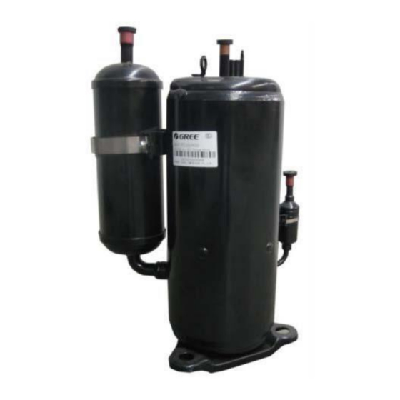
5.3 Repair 5.3.1 Main Parts Picture Name Function It is the core of the refrigeration system, which is mainly used to convert low-temperature, low-pressure refrigerant vapour to high- temperature high-pressure vapour and then discharge it into the Compressor evaporator. Here, a two-stage compressor is used to increase the enthalpy of the refrigerant, which can greatly improve the heating performance of the unit. - Page 147 Picture Name Function It is used in the Heating mode and Water Heating mode, but NOT used in the Cooling mode. On the one side, it can increase the Economizer subcooling before the expansion valve, and, on the other side, it can heat the refrigerant in the heating circuit.
- Page 148 Note: Before and during the operation, use a suitable refrigerant leak detector to monitor the work area and ensure that technicians are fully aware of the potential and actual danger of a flammable refrigerant leak. Make sure that the leak detection equipment is suitable for the flammable refrigerant.
- Page 149 4. Open the lower panel. You will see the location of the anode rod and the water drain valve. Open the water drain valve and drain the water from the tank. Anode rod Water drain valve 5. Remove the anode rod cover attached to the water tank.
- Page 150 6. Use a Phillips screwdriver to remove 1 screw that secures the power cord. 7. Use a wrench to unscrew the old anode rod counterclockwise and remove it. 8. Install a new anode rod by performing steps 1–7 in reverse order.
- Page 151 WC2B 5AH London United Kingdom www.sinclair-world.com This product was manufactured in China (Made in China). R E P R E S E N T A T I V E SINCLAIR Global Group s.r.o. Purkynova 45 612 00 Brno Czech Republic TECHNICAL SUPPORT SINCLAIR Global Group s.r.o.
Need help?
Do you have a question about the S-THERM GSH-160ERB and is the answer not in the manual?
Questions and answers