
Related Manuals for Sinclair STHERM GSH-80IRB


Summary of Contents for Sinclair STHERM GSH-80IRB
- Page 1 INSTALLATION MANUAL SPLIT AIR TO WATER HEAT PUMPS GSH-80IRB + GSH-80ERB GSH-100IRB + GSH-100ERB H E A T P U M P S...
- Page 2 To Users Thank you for selecting Sinclair product. Please read this instruction manual carefully before installing and using the product, so as to master and correctly use the product. In order to guide you to correctly install and use our...
-
Page 3: Table Of Contents
Contents Safety Notices (Please be sure to abide ) ..............1 1. Diagram of the Operating Principle ................. 8 2. Operating Principle of the Unit ................. 8 3. Nomenclature......................10 4. Installation Example ..................... 11 5. Main Components ....................14 5.1 Indoor unit ........................14 5.2 Outdoor unit ........................16 6. - Page 4 18.2 Outline dimension and parameter of water tank ............32 18.3 Connection of waterway system ...................33 18.4 Electric wiring work ......................34 19. Wring Diagram ....................... 36 19.1 Control Board ........................36 19.2 Electric Wiring .......................42 20. Commissioning...................... 44 20.1 Check before startup .....................44 20.2 Test run .........................46 21.
-
Page 5: Safety Notices (Please Be Sure To Abide )
Safety Notices (Please be sure to abide ) WARNING: If not abide strictly, it may cause severe damage to the unit or the people. NOTE: If not abide strictly, it may cause slight or medium damage to the unit or the people. - Page 6 WARNING Once abnormality Don't operate the unit with Before likeburning smell occurs, wet hand. installation,please see please cut off the power if the voltage of local supply immediately and place accords with then contact with service that on nameplate center. of unit and capacity of power supply, power cord or socket...
- Page 7 Before cleaning please cut The power supply must User can not change off the power supply. adopt special circuit with power cord socket leakage switch and enough without prior consent. capacity. Wiring working must be done by professionals. Ensure good earthing and don't change earthing mode of unit.
- Page 8 Don't step on the top of the Never block the air inlet and Keep pressurized unit or place anything on it. outlet of unit. spray, gas holder and so on away from the unit above 1m . There is the danger of fall of things or people.
- Page 9 WARNING Do not use means to accelerate the defrosting process or to clean, other than those recommended by the manufacturer. Should repair be necessary, contact your nearest authorized service centre. Any repairs carried out by unqualified personnel may be dangerous. The appliance shall be stored in a room without continuous operating ignition sources.
- Page 10 To realize the function of the air conditioner unit, a special refrigerant circulates in the system. The used refrigerant is the fluoride R32, which is specially cleaned.The refrigerant is flammable and inodorous. Furthermore, it can leads to explosion under certain conditions. But the flammability of the refrigerant is very low. It can be ignited only by fire.
- Page 11 maximum and minimum water operating temperatures. Maximum Minimum water operating Item water operating temperatures temperatures Cooling 7°C 25°C Heating 20°C 60°C Water heating 40°C 80°C maximum and minimum water operating pressures. Minimum water operating Maximum water Item pressures operating pressures Cooling Heating 0.05MPa...
-
Page 12: Diagram Of The Operating Principle
1. Diagram of the Operating Principle Indoor Unit Outdoor Unit Field Supply Ambient Temp. Sensor Defrost temp. sensor Fin-tube Other thermal heat exchanger EXV 1 EXV 2 T-economizer in 4-way valve High pressure sensor Safety High pressure vavle switch 3-Way Optional T-water out T-optional... - Page 13 the required range. Water heating: in water heating mode: the refrigerant evaporates in the outdoor unit and is condensed in the indoor unit. Via the heat exchange with water in the indoor unit, the water absorbs heat and its temperature increase while the refrigerant releases heat and is condensed.
-
Page 14: Nomenclature
3. Nomenclature Model Line-Up Capacity Model name Power supply Heating, kW Cooling, kW GSH-80IRB + GSH-80ERB 230VAC 50 Hz GSH-100IRB + GSH-100ERB Notes Capacities and power inputs are based on the following conditions: Indoor Water Temperature 30°C/35°C, Outdoor Air Temperature 7°C DB/6°C WB; Capacities and power inputs are based on the following conditions: Indoor Water Temperature 23°C/18°C, Outdoor Air Temperature 35°C DB/24°C WB. -
Page 15: Installation Example
4. Installation Example CASE 1: Connecting Under-floor Coil for Heating and Cooling Notes (a) The two-way valve is very important to prevent dew condensation on the floor while cooling mode; (b) Type of thermostat and specification should be complied with installation of this manual; (c) The bypass valve must be installed to secure enough water flow rate, and should be installed at the collector. - Page 16 CASE 2: Connecting Sanitary Water Tank and Under-floor Coil Notes (a) The two-way valve is very important to prevent dew condensation on the floor while cooling mode (b) In this case, three-way valve should be installed and should be complied with installation of this manual; (c) Anitary water tank should be equipped with internal electric heater to secure enough heat energy in the very cold days.
- Page 17 CASE 3 : Connecting Sanitary Water Tank, Under-floor Coil and FCU Notes (a) The two-way valve is very important to prevent dew condensation on the floor and FCU while cooling mode (b) In this case, three-way valve should be installed and should be complied with installation of this manual; (c) Anitary water tank should be equipped with internal electric heater to secure enough heat energy in the very cold days.
-
Page 18: Main Components
5. Main Components 5.1 Indoor unit GSH-80IRB, GSH-100IRB External Plate heat exchanger Air vent Electric heater Control box Expansion tank Water pressure gauge Safety valve Water pump 3-way valve Flow switch Control panel Internal... -
Page 19: Outdoor Unit
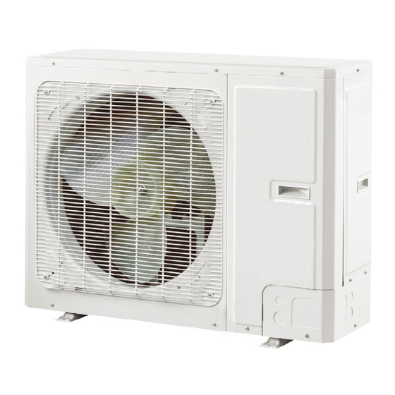
5.2 Outdoor unit GSH-80ERB, GSH-100ERB External Control Box DC Fan Motor Compressor Internal... -
Page 20: Installation Guideline Of Outdoor Unit
6. Installation Guideline of Outdoor Unit 6.1 Instruction to installation (1) Installation of the unit must be in accordance with national and local safety codes. (2) Installation quality will directly affect the normal use of the air conditioner unit. The user is prohibited from installation. - Page 21 Description: Unit: inch Name Remarks Liquid-side Service Valve GSH-80ERB, GSH-100ERB Gas-side Service Valve Handle Used to cover or uncover the front casew Air discharge Grill 6.2.3 Space requirements for installation Wall Wall >500 > 1000 > 500 >500 > 500 >2000 >2000 Wall...
-
Page 22: Installation Of Indoor Unit
7. Installation of Indoor Unit 7.1 Select installation location of indoor unit (1) Avoid direct sunshine. (2) Ensure the hanger rod, ceiling and building structure have sufficient strength to support the weight of air conditioner unit. (3) Drainage pipe is easy to connect out. (4) Indoor and outdoor connection pipes are easy to go outdoors. -
Page 23: Installation Process Of Indoor Unit
7.3 Installation process of indoor unit Step1:Drilling hole on the wall in the following draw. Wall Wall Step2:Install expansion bolts and forecasted pannel. Support Expansion bolt X3 Wall Wall Step3: Attaching indoor unit to the wall. Wall Thermal baffle Note NOTE •... -
Page 24: Outline Dimension Of Indoor Unit
7.4 Outline dimension of indoor unit Description: Unit: inch Name Remarks Leaving Water Pipe 1″Male BSP Returning Water Pipe 1″Male BSP Gas-side Pipe GSH-80IRB, GSH-100IRB Liquid-side Pipe 7.5 Precautions on installation of indoor unit (1) Indoor unit shall be vertically mounted on the wall of the room with expansion bolt. (2) Keep the indoor unit away from heat sources like heat sink and so on in the room as much as possible. -
Page 25: Water Volume And Expansion Vessel Pressure
7.7 Water volume and expansion vessel pressure Maximum total water volume(liter) Notes (a) The expansion vessel is 10 liter and 1bar pre-pressurized; (b) Total water volume of 280 liter is default; if total water is changed because of installation condition, the pre- pressure should be adjusted to secure proper operation. -
Page 26: Connection Of Pipeline
0.0198 0.0227 0.0258 0.029 0.0324 0.0359 0.0396 0.0434 8. Connection of Pipeline 8.1 Connection of outlet pipe for indoor & outdoor unit (1) Align the expansion end of copper pipe with the center of threaded joint. Tighten the flaring nuts with your hands. - Page 27 No clearance Indoor unit Outdoor unit Indoor unit Outdoor unit Outdoor unit Indoor unit Oil bend Pipe size Length B Elevation A Additional (Diameter:Φ) Model refrigerant Liquid Standard Max. Standard Max. GSH-80ERB 1/2" 1/4" 16g/m GSH-100ERB 1/2" 1/4" 16g/m Notes (a) No additional charge of the refrigerant is need when the pipe length is less than 10m, if the pipe length is...
-
Page 28: Remote Air Temperature Sensor
longer than 10m, additional charge of the refrigerant is needed according to the table. (b) Example: If 10kW model is installed at a distance of 25m, (25-10)x16=240g refrigerant should be added. Rated capacity is based on standard pipe length and maximum allowable length is based on the product reliability in the operation. -
Page 29: Thermostat
(d) Remote air temperature sensor cannot be located where external thermal influence may be applied; (e) Remote air temperature sensor should be installed where space heating is mainly applied; (f) After the remote air temperature sensor is installed, it should be set to “With” through the wired controller so as to set the remote air temperature to the control point. -
Page 30: Other Auxiliary Heat Sources
N(1) N(1) N(1) 2-Way 2-Way 2-Way valve 1 valve 1 valve 1 WARNING • Normal Open type should be connected to wire (OFF) and wire (N) for valve closing in cooling mode. • Normal Closed type should be connected to wire (ON) and wire (N) for valve closing in cooling mode. (ON) : Line signal (for Normal Open type) from PCB to 2-way valve (OFF) : Line signal (for Normal Closed type) from PCB to 2-way valve (N) : Neutral signal from PCB to 2-way valve... - Page 31 Step 1. Other thermal installation Other thermal should be installed with monobloc unit parallel.Moreover,an accessory called optional water temperature sensor(5 meter length) shall be installed at the same time. Other thermal Indoor Unit Safety 3-Way Optional 2-Way vavle Valve 2 T-water out T-optional 3-way...
-
Page 32: Gate-Controller
14. Gate-controller If there is gate control function, installation guide follow as: 13 14 220~50Hz Gate-controller 15. Charging and Discharging of Refrigerant (1) Before shipped out from manufacturer, the outdoor unit has been filled with refrigerant. Additional refrigerant may be filled when carrying out site connection of pipelines. (2) Check the liquid valve and the gas valve of the outdoor unit. -
Page 33: Refrigerant Collecting
16. Refrigerant Collecting When relocating or disposing of the indoor/outdoor unit, pump down the system following the procedure below so that no refrigerant is released into the atmosphere. (1) Turn off the power supply (circuit breaker). (2) Connect the low-pressure valve on the gauge manifold to the charge plug (lowpressure side) on the outdoor unit. -
Page 34: Installation Of Insulated Water Tank
supply is cut off before disassembling the connection pipe. If connection pipe is disassembled when the compressor is still operating, air may get into the system. In this case, system pressure will increase and compressor will be damaged. During installing the unit, make sure the connection pipe is connected properly before starting the compressor. If the compressor is started before finishing connection of connection and when the cut-off valve is opened, air may get into the system. -
Page 35: Connection Of Waterway System
Joints Dimension Description Joint pipe thread Hot water outlet of water tank 1/2″Female BSP Circulating water inlet/outlet of water tank 3/4″Female BSP Cooling water inlet of water tank 1/2″Female BSP Pipe joint 3/4″Female BSP 18.3 Connection of waterway system (1) If connection between water tank and indoor unit should be through the wall, drill a hole φ70 for pass of circulating water pipe. -
Page 36: Electric Wiring Work
Description Joint pipe thread Circulating water inlet/outlet of main unit 1″Male BSP Cooling water inlet of water tank 1/2″Female BSP Circulating water inlet/outlet of water tank 3/4″Female BSP Hot water outlet of water tank 1/2″Female BSP Notes (a) Distance between indoor unit and water tank should not exceed 5m levelly and 3m vertically. If higher, please contact with us. - Page 37 18.4.2 Specification of power supply wire and leakage switch Power cable specifications and Leakage switch types in the following list are recommended. Minimum Leakage Minimum Sectional Sectional Area Power Supply Switch Area of Earth Wire of Power Supply Model Wire V,Ph,Hz GSH-80ERB GSH-100ERB...
-
Page 38: Wring Diagram
19. Wring Diagram 19.1 Control Board GSH-80ERB, GSH-100ERB AP1 Indoor unit Main Board CN20 AC_L CN21 CN22 CN23 CN24 CN25 CN10 CN16 CN1 5 CN19 CN18 Silk Screen Introduction Live wire of power supply AC-L Neutral wire of power supply To the ground E-heater of water tank E-heater 1... - Page 39 Reserved Reserved Reserved Reserved 3-way valve signal CN30 Build-in water pump signal(PWM) CN31 Back-up water pump signal(PWM)-field supply CN18 20K temperature sensor (inlet water) CN19 20K temperature sensor (outlet water) CN15 20K temperature sensor (refrigerant liquid line) CN15 20K temperature sensor (outlet water) CN15 20K temperature sensor (refrigerant liquid line) CN16...
- Page 40 AP2 Outdoor unit Main Board AC-L AC-N HEAT VA-1 H_PRES S COM- ES PE1 COM- ES PE2 PWR1 DC-M OTORO1 DC-M OTORO T-SE NSOR3 T-SE NSOR2 T-SE NSOR1 Silk Screen Introduction AC-L Live wire of power supply Neutral wire of power supply PWR1 Reserved Fuse...
- Page 41 AP3 Drive Board N-OUT COMM L-OUT AC -L Silk Screen Introduction AC-L Live line input Neutral line input L-OUT Live line output N-OUT Neutral line output COMM Communication To compressor phase U To compressor phase V To compressor phase W...
-
Page 42: Electric Wiring
19.2 Electric Wiring 19.2.1 Wiring principle Refer to Section 18.4. 19.2.2 Electric wiring design The wiring diagram stuck to the unit always prevails. Wiring diagram: indoor unit GSH-80IRB, GSH-100IRB... - Page 43 Wiring diagram: outdoor unit GSH-80ERB, GSH-100ERB •...
-
Page 44: Commissioning
19.2.3 Terminal Board GSH-80IRB, GSH-100IRB Terminal board XT2 N(1) 2-Way-valve1 Other thermal Terminal board XT1 Teminal board XT3 10 11 14 15 Power Water tank Auxiliary Thermostat Gate- Pump control Supply electric heater controller signal(OUT) 20. Commissioning 20.1 Check before startup For safety of users and unit, the unit must be started up for check before debugging. - Page 45 Does power supply accord with the nameplate? Do power cords conform to applicable requirements? □ Is power supply and control wiring connected properly according to wiring diagram? Is earthing safe? Is □ each terminal stable? Are connection pipe, water pump, manometer, thermometer, valve etc. are installed properly? □...
-
Page 46: Test Run
20.2 Test run Test run is testing whether the unit can run normally via preoperation. If the unit cannot run normally, find and solve problems until the test run is satisfactory. All inspections must meet the requirements before performing the test run. -
Page 47: Daily Operation And Maintenance
Therefore, once the water tank has been installed, the water tank must be set to ‘’With”, otherwise Sinclair will not be responsible for this abnormal operation. Never frequently make the unit on/off and close the manual valve of the water system during operation of the unit by users. -
Page 48: Recovery
21.1 Recovery When removing refrigerant from a system, either for servicing or decommissioning, it is recommended good practice that all refrigerants are removed safely. When transferring refrigerant into cylinders, ensure that only appropriate refrigerant recovery cylinders are employed. Ensure that the correct number of cylinders for holding the total system charge are available. All cylinders to be used are designated for the recovered refrigerant and labelled for that refrigerant (i.e. -
Page 49: Safety Consideration
21.3 Safety consideration Checking for presence of refrigerant The area shall be checked with an appropriate refrigerant detector prior to and during work, to ensure the technician is aware of potentially toxic or flammable atmospheres. Ensure that the leak detection equipment being used is suitable for use with all applicable refrigerants, i.e. -
Page 50: Notice Before Seasonal Use
21.4 Notice before Seasonal Use (1)Check whether air inlets and air outlets of indoor and outdoor units are blocked; (2)Check whether ground connection is reliable or not; (3)If unit starts up after not operating for a long time, it should be power on 8 hours before operation starts so as to preheat the outdoor compressor;... - Page 51 NOT CONC RNING PROT CTION OF NVIRONM NT INFORM TION CONC RNING R FRIG R NT IR CORPOR TION R PR NT TIV T C NIC PPORT...
Need help?
Do you have a question about the STHERM GSH-80IRB and is the answer not in the manual?
Questions and answers