Advertisement
S87A,B,C,D,J,K
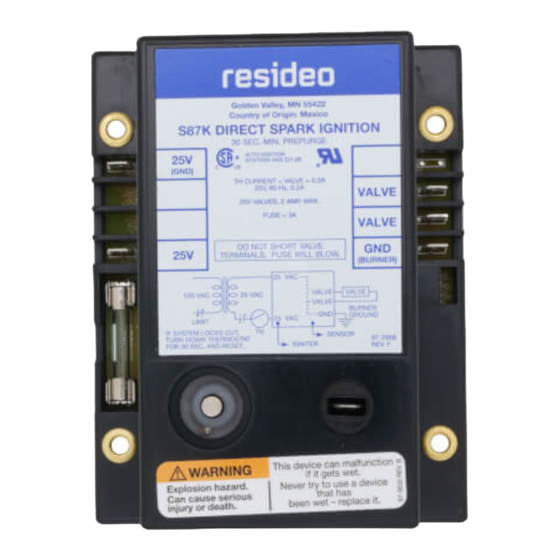
DIRECT SPARK IGNITION CONTROL MODULE
APPLICATION
The S87 is a low voltage, solid state, direct spark ignition
control module for gas-fired furnaces, boilers and heating
appliances. Models are available with or without a prepurge
timer. The S87 controls the gas valve, monitors the main
burner flame and generates a high voltage for spark ignition.
INSTALLATION INSTRUCTIONS
FEATURES
• S87A uses a single electrode for spark ignition and flame
sensing. Use only with Resideo gas controls designed for
OSI application: V845, V854, VR845, VR854, VR8450 and
VR8540.
• S87B uses a single electrode for spark ignition and flame
sensing. Use with any gas control designed for OSI
application that is rated at 2.0 A or less. Includes optional
alarm circuit for use on system safety lockout
• S87C uses separate electrodes for spark ignition and
flame sensing. Use only with Resideo gas controls
designed for OSI application: V845, V854, VR845, VR854,
VR8450 and VR8540. For direct replacement of S825C.
See page 3.
• S87D uses separate electrodes for spark ignition and
flame sensing. Use with any gas control designed for OSI
application that is rated at 2.0 A or less. Includes optional
alarm circuit. For direct replacement of S825D. See page
3.
• S87J uses a single electrode for spark ignition and flame
sensing. Use with any gas control designed for OSI
application that is rated at 2.0 A or less. Includes a 30
second (minimum) delay for use with system prepurge.
• S87K uses separate electrodes for spark ignition and
flame sensing. Use with any gas control designed for OSI
application that is rated at 2.0 A or less. Includes a 30
second (minimum) delay for use with system prepurge.
• External, replaceable fuse protects system transÂformer
and temperature controller.
• Automatic system lockout after trial-for-ignition if
malfunction exists or main burner flame fails to ignite. All
models available with 4, 6, 11, or 21 second (nominal)
lockout time.
• Compact, solid state components for accurate, long-
lasting performance.
• Convenient remote start procedure; after safety
shutdown, control module can be reset from the
temperature controller.
• Low voltage control circuit reduces wiring costs.
• Uses flame rectification principle to prove presence of
main burner flame; false flame signal resulting from short
to ground results in safety shutdown.
68-0039-02
Advertisement
Table of Contents

Related Manuals for resideo S87K


Summarization of Contents
APPLICATION
S87 Application Overview
Direct spark ignition control for gas-fired appliances. Controls gas valve, monitors flame, generates spark.
FEATURES
S87A Single Electrode Operation
Single electrode for spark ignition and flame sensing with Resideo gas controls.
S87B Single Electrode Operation
Single electrode for spark ignition/flame sensing with OSI application, optional alarm.
S87C Separate Electrode Operation
Separate electrodes for spark ignition/flame sensing with Resideo gas controls.
S87D Separate Electrode Operation
Separate electrodes for spark ignition/flame sensing with OSI application, optional alarm.
S87J Single Electrode with Pre-purge
Single electrode for spark ignition/flame sensing with OSI application, 30 sec prepurge.
S87K Separate Electrode with Pre-purge
Separate electrodes for spark ignition/flame sensing with OSI application, 30 sec prepurge.
External Fuse Protection
Protects system transformer and temperature controller.
Automatic System Lockout
Lockout after trial-for-ignition if malfunction exists or flame fails.
Remote Reset Capability
Module can be reset from the temperature controller after safety shutdown.
Flame Rectification Principle
Proves flame presence; short-to-ground causes shutdown.
SPECIFICATIONS
Electrical Ratings
Voltage, current, valve, and alarm contact ratings.
Safety Lockout Timing
Nominal lockout times: 4, 6, 11, 21 seconds.
Flame Current Requirement
Minimum 1.5 µ dc for flame signal.
Ignition Cable Specifications
Type, max length 3 ft, snap-spring connectors.
Ambient Temperature Limits
Operating range from -40 F to 175 F [-40 C to 79 C].
INSTALLATION
Mounting the S87 Control Module
Select location within 3 ft of burner, allow direct cable route, ensure terminal access.
Mounting Auxiliary Controls
Mount spark igniter, flame sensor, thermostat, transformer, gas control per manufacturer instructions.
WIRING
Wiring General Precautions
Check diagrams, comply with codes, disconnect power, keep sensor leads short.
Wiring the S87 Control Module
Connect system components to S87 terminals per diagrams, refer to appliance instructions.
Thermostat Heat Anticipator Adjustment
Match heat anticipator to system current draw (S87 + valve + loads).
Grounding System Components
Ensure common ground for system components via burner; use thermoplastic wire.
STARTUP AND CHECKOUT
Gas Leak Test Procedure
Test for gas leaks after gas control replacement using soap solution.
System Startup Procedure
Turn on power/gas, set thermostat for heat, check for spark and ignition.
Safety Lockout Check
Test lockout by manually shutting off gas and timing spark cutoff.
Resetting After Safety Lockout
Adjust thermostat below room temp for 30s, then call for heat.
Post-Installation Checkout
Observe operation through a complete cycle for safety.
OPERATION
Pre-purge Function (S87J/K)
S87 J and K models provide a 30-second minimum system pre-purge.
Spark Ignition Power Supply
Provides 30,000 volts for spark igniter.
Trial-for-Ignition Period
Maximum 35 seconds for ignition before safety lockout.
Flame Sensing
Monitors burner flame current for safe operation.
Spark Shutdown
Spark is turned off once flame is established.
Activation by Thermostat
Activated by a thermostat call for heat.
System Ignition and Gas Flow
Powers spark ignition and opens gas valves upon thermostat call.
Spark Generator Power Termination
Spark stops when flame is sensed or lockout timing ends.
Preliminary Check
Pre-Troubleshooting Checks
Verify power, fuse, gas supply, wiring connections, lockout status, and component condition.
S87 Component Checks
Spark Ignition Circuit Check
Check for 30,000V spark output at the S87 stud terminal.
Ignition Cable Inspection
Check electrical continuity, contact with metal surfaces, and length.
Grounding Connections Check
Verify clean and tight electrical ground connections at igniter/sensor and S87.
Flame Sensor Circuit Test
Measure flame sensing current (min 1.5 µA) using a meter.
TROUBLESHOOTING
Low or Unsteady Flame Current
Check burner flame, sensor location, and electrical connections for low flame current.
Burner Flame Conditions
Check burner flame for proper immersion and characteristics.
Flame Sensor Positioning
Ensure flame sensor is immersed about 1 in. in the burner flame.
Electrical Connections and Shorts
Ensure clean, tight connections at flame sensor; use proper wire.
Post-Service Checkout
Perform startup, lockout check, and reset after service.
REPLACING S825 WITH S87
Choosing the Correct Replacement
Select S87 with the same lockout timing as the old control.
Disconnecting Wires
Disconnect ignition cable and sensor wire from the old S825.
Labeling and Terminal Disconnection
Label leads from S825 terminals before disconnecting.
Removing the Old Module
Remove the old S825 module from its mounting.
Mounting the New S87 Module
Mount the S87 in the same location using appropriate screws.
Wire and Cable Checks
Check wires and ignition cable for damage; ensure proper grounding.
System Grounding Verification
Ensure system is firmly grounded to the burner.
Connecting Ignition and Sensor Wires
Connect ignition cable and sensor wire to the S87 terminals.
Wiring Conversion Charts
Use cross-reference charts for S87 wiring based on old S825 model.
Need help?
Do you have a question about the S87K and is the answer not in the manual?
Questions and answers