Advertisement
S87A,B,C,D,J,K
DIRECT SPARK IGNITION CONTROL MODULE
APPLICATION
The S87 is a low voltage, solid state, direct spark ignition
control module for gas-fired furnaces, boilers and heating
appliances. Models are available with or without a prepurge
timer. The S87 controls the gas valve, monitors the main
burner flame and generates a high voltage for spark ignition.
INSTALLATION INSTRUCTIONS
FEATURES
• S87A uses a single electrode for spark ignition and flame
sensing. Use only with Resideo gas controls designed for
OSI application: V845, V854, VR845, VR854, VR8450 and
VR8540.
• S87B uses a single electrode for spark ignition and flame
sensing. Use with any gas control designed for OSI
application that is rated at 2.0 A or less. Includes optional
alarm circuit for use on system safety lockout
• S87C uses separate electrodes for spark ignition and
flame sensing. Use only with Resideo gas controls
designed for OSI application: V845, V854, VR845, VR854,
VR8450 and VR8540. For direct replacement of S825C.
See page 3.
• S87D uses separate electrodes for spark ignition and
flame sensing. Use with any gas control designed for OSI
application that is rated at 2.0 A or less. Includes optional
alarm circuit. For direct replacement of S825D. See page
3.
• S87J uses a single electrode for spark ignition and flame
sensing. Use with any gas control designed for OSI
application that is rated at 2.0 A or less. Includes a 30
second (minimum) delay for use with system prepurge.
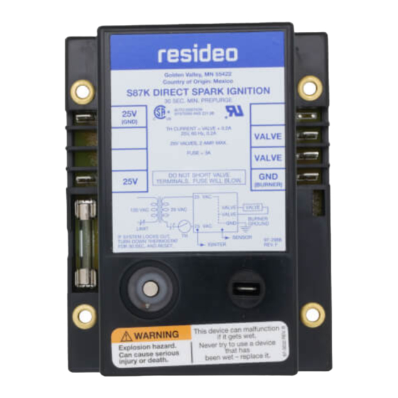
• S87K uses separate electrodes for spark ignition and
flame sensing. Use with any gas control designed for OSI
application that is rated at 2.0 A or less. Includes a 30
second (minimum) delay for use with system prepurge.
• External, replaceable fuse protects system transÂformer
and temperature controller.
• Automatic system lockout after trial-for-ignition if
malfunction exists or main burner flame fails to ignite. All
models available with 4, 6, 11, or 21 second (nominal)
lockout time.
• Compact, solid state components for accurate, long-
lasting performance.
• Convenient remote start procedure; after safety
shutdown, control module can be reset from the
temperature controller.
• Low voltage control circuit reduces wiring costs.
• Uses flame rectification principle to prove presence of
main burner flame; false flame signal resulting from short
to ground results in safety shutdown.
68-0039-02
Advertisement
Table of Contents

Subscribe to Our Youtube Channel
Related Manuals for resideo S87A


Summary of Contents for resideo S87A
- Page 1 S87A,B,C,D,J,K DIRECT SPARK IGNITION CONTROL MODULE INSTALLATION INSTRUCTIONS FEATURES • S87A uses a single electrode for spark ignition and flame sensing. Use only with Resideo gas controls designed for OSI application: V845, V854, VR845, VR854, VR8450 and VR8540. • S87B uses a single electrode for spark ignition and flame sensing.
-
Page 2: Specifications
Table 1 for recommended flame sensors. Table 1. S87 Models. Model No. Spark Igniter Flame Sensor Valve Required S87A Resideo V845, V854, VR845, VR854, VR8450, VR8540 Q347B Any DSI valve rated up to 2.0 A maximum S87B Q347B Q347A or Q330 (1) Q354A... -
Page 3: Installation
S87A,B,C,D,J,K Relative Humidity Rating: 5 to 95 percent at 90 F [32 C]. 3. The installer must be a trained, experienced service technician. Prepurge Timing (S87J,K): 30 seconds, minimum; 4. After installation is complete, check out system opera- 45 seconds, maximum. -
Page 4: General Precautions
2. Adjust thermostat heat anticipator to match system current draw. The current draw equals the total current Fig. 2. S87A in typical hookup for direct spark ignition required for the S87 (0.2 A) plus the gas valve and all heating system. See Fig. 14 for system schematic diagram. - Page 5 S87A,B,C,D,J,K Fig. 3. S87B in typical hookup for direct spark ignition heating system. See Fig. 15 for system schematic diagram. Fig. 4. S87C in typical hookup for direct spark ignition heating system. See Fig. 16 for system schematic diagram. 68-0039—02...
- Page 6 S87A,B,C,D,J,K Fig. 5. S87D in typical hookup for direct spark ignition heating system. See Fig. 17 for system schematic diagram. Fig. 6. S87J in typical hookup for direct spark ignition heating system with prepurge blower connection. See Fig. 18 for system schematic.
- Page 7 S87A,B,C,D,J,K Fig. 7. S87K in typical hookup for direct spark ignition heating system with prepurge blower connection. See Fig. 19 for system schematic. 68-0039—02...
- Page 8 S87A,B,C,D,J,K Fig. 8. S87 in typical heat-cool application with direct spark ignition heating system. Fig. 9. S87 in typical two-stage direct spark ignition heating system. 68-0039—02...
-
Page 9: Startup And Checkout
S87A,B,C,D,J,K STARTUP AND CHECKOUT Table 4. S87 Lockout Times. Specified S87 Lockout Time The following start-up and checkout procedures are basic to (stamped on S87 control Safety Lockout Time Should all S87 control modules. If this is a replacement application,... - Page 10 S87A,B,C,D,J,K If the main burner lights, a flame sensing circuit is completed When the system goes into safety lockout, power to the spark through the flame to the burner head to ground. This current generator is interrupted, the gas control circuit is interrupted flow sets the safety lockout timer to the reset (normal) and the alarm circuit (S87B and D only) is completed.
- Page 11 S87A,B,C,D,J,K Fig. 10. Normal system sequence of operation. onds before recycling for further tests. SERVICE 4. Always turn off gas supply before performing igni- tion checks. IMPORTANT 5. S87 control module cannot be repaired. If the trou- 1. Only persons trained and experienced in OSI sys- bleshooting procedure indicates a malfunction in tems should service this equipment.
-
Page 12: Preliminary Check
S87A,B,C,D,J,K 4. A spark length of 1/8 inch [3 mm] or more indicates Preliminary Check satisfactory voltage output. If no arc can be estab- The following checks should be made before troubleshooting lished or the maximum spark is less than 1/8 in. -
Page 13: Troubleshooting
S87A,B,C,D,J,K BURNER FLAME The flame sensor must be constantly immersed in flame. Check burner flame conditions as shown in Fig. 12. FLAME SENSOR The flame signal is best when about 1 in. [25 mm] of flame rod is immersed in the burner flame. A bent flame rod, bent mounting bracket or cracked ceramic insulator can affect flame signal. - Page 14 S87A,B,C,D,J,K Fig. 13. S87 direct spark ignition system. 68-0039—02...
- Page 15 S87A,B,C,D,J,K S87 Schematic Diagrams Fig. 14. S87A simplified system schematic. Fig. 15. 587B simplified system schematic. 68-0039—02...
- Page 16 S87A,B,C,D,J,K Fig. 16. S87C simplified system schematic. Fig. 17. S87D simplified system schematic. 68-0039—02...
- Page 17 S87A,B,C,D,J,K Fig. 18. S87J simplified system schematic. 68-0039—02...
- Page 18 S87A,B,C,D,J,K Fig. 19. S87K simplified system schematic. REPLACING S825 WITH S87 To Replace S825A S87C or D WARNING S825B S87D The replacement S87 must have the same lockout S825C S87C or D timing as the old control to avoid possible explosion...
- Page 19 S87A,B,C,D,J,K 6. Check the wires and ignition cable. Replace any wires that appear cracked or damaged. Lead from S825D Terminal Connect to S87D Terminal 7. Make sure the system is firmly grounded to the burner. ALARM A screw is provided on most burners to simplify grounding.
- Page 20 Resideo Technologies, Inc. 1985 Douglas Drive North, Golden Valley, MN 55422 1-800-468-1502 68-0039—02 M.S. Rev. 06-20 | Printed in United States www.resideo.com © 2020 Resideo Technologies, Inc. All rights reserved. This product is manufactured by Resideo Technologies, Inc. and its affiliates.
Need help?
Do you have a question about the S87A and is the answer not in the manual?
Questions and answers