Table of Contents
Advertisement
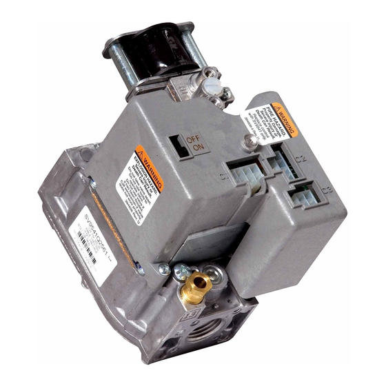
SV9540; SV9640
SmartValve™ System Controls
APPLICATION
The SV9540; SV9640 SmartValve™ System Controls
combine gas flow control and electronic intermittent
pilot sequencing functions into a single unit. The low
voltage igniter, flame sensor and pilot burner are
supplied by the Q3450 or Q3480 Pilot Hardware.
Provides all gas ignition safety functions by controlling
gas flow, ignition source, and a 120 Vac or 240 Vac
combustion air blower. The control also monitors the
appliance airflow proving switch and limit string to
assure proper appliance operation. Provides prepurge,
postpurge, timed trial for pilot igniton, with 100 percent
shutoff and continuous retry. Diagnostic LED indicates
system status.
This control communicates directly with the ST9160
Electronic Fan Timer (EFT) in typical forced warm air
furnace applications. It also interfaces with the 208907
Terminal Board, providing compatibility with power
stealing thermostats. Or, it directly interfaces with the
appropriate power supplies and a system thermostat for
additional appliance applications. When controlled
directly by a thermostat, the control does not provide a
postpurge function, as power to the control is removed
when the thermostat call for heat ends.
The SV9540; SV9640 system is suitable for a wide range
of fan assisted combustion gas-fired appliances
including furnaces, rooftop furnaces, boilers, unit
heaters, infrared heaters, water heaters and commercial
cooking appli-ances. The specific application of the
SmartValve System is the responsibility of the appliance
manufacturer. See Table 1 for temperature ranges and
regulator types.
INSTALLATION INSTRUCTIONS
SPECIFICATIONS
CAUTION
The SV9540; SV9640 provide direct replacement
only. Use the Y8610 to convert standing pilot
systems to electronic ignition systems.
Table 1. Model Number Suffix Letter Designation.
Model No.
Suffix
Temperature
Letter
H
0°F to 175°F
(-18°C to +79°C)
M
-40°F to 175°F
(-40°C to +79°C)
P
40°F to175°F
(-40°C to +79°C)
Body Pattern:
SV9540: Straight through with 1/2 in. inlet and 1/2 in.
outlet; or 1/2 in. NPT inlet and 1/2 in. inverted flare
outlet.
SV9640: Straight through with 1/2 in. inlet and 1/2 in.
outlet, 1/2 in. inlet and 3/4 in. outlet, or 3/4 in. inlet
and 3/4 in. outlet.
Electrical Ratings:
System Transformer:
SV9540: 40 VA minimum NEMA rated.
SV9640: 40 VA minimum NEMA rated.
NOTE:
Larger system transformer may be required for
specific applications.
Voltage and Frequency:
24 Vac, 60 Hz; 50 Hz models available.
Output Ratings:
Igniter Load: 1.5A maximum.
Induced Draft Motor Load: 2.5A Full Load, 10A
Locked Rotor at 120 Vac; 1.75A Full Load, 5A
Locked Rotor at 240 Vac.
Current at 24 Vac:
24V Thermostat: See Table 2.
Ambient
Pressure
Range
Regulator Type
Slow-opening
Standard
Step-opening
69-1059-01
Advertisement
Table of Contents

Related Manuals for resideo SmartValve SV9540


Summary of Contents for resideo SmartValve SV9540
- Page 1 SV9540; SV9640 SmartValve™ System Controls INSTALLATION INSTRUCTIONS APPLICATION SPECIFICATIONS The SV9540; SV9640 SmartValve™ System Controls CAUTION combine gas flow control and electronic intermittent pilot sequencing functions into a single unit. The low The SV9540; SV9640 provide direct replacement voltage igniter, flame sensor and pilot burner are only.
- Page 2 SMARTVALVE™ SYSTEM CONTROLS Minimum: 40,000. Maximum: 200,000. Table 2. Thermostat Current (Run Mode); with control connected directly to thermostat. SV9540 with 1/2 in. Inverted Flare Outlet: Model 24 Vac, 60 Hz Natural Gas: Minimum: 20,000. SV9540 0.25A Maximum: 180,000. SV9640 0.25A LP Gas: Minimum: 40,000.
-
Page 3: Planning The Installation
1. Read these instructions carefully. Failure to follow or excessive heat. These applications require Resideo them could damage the product or cause a hazard- Engineering review; contact your Sales Representative ous condition. -
Page 4: Install Adapters To Control
SMARTVALVE™ SYSTEM CONTROLS Flanges WARNING 1. Choose the appropriate flange for your application. FIRE OR EXPLOSION HAZARD CAN CAUSE 2. Remove the seal over the ignition system control PROPERTY DAMAGE, SEVERE INJURY OR DEATH inlet or outlet. Follow these warnings exactly: 3. -
Page 5: Install Piping To Control
SMARTVALVE™ SYSTEM CONTROLS 3. Thread the pipe the amount shown in Table 6 for Install Piping to Control insertion into ignition system control or adapters. All piping must comply with local codes and ordinances Do not thread pipe too far. Valve distortion or mal- or with the National Fuel Gas Code (ANSI Z223.1 NFPA function can result if the pipe is inserted too No. - Page 6 SMARTVALVE™ SYSTEM CONTROLS WHEN FLANGE IS USED WHEN FLANGE IS NOT USED APPLY WRENCH TO FLANGE ONLY APPLY WRENCH FROM TOP OR BOTTOM OF IGNITION SYSTEM CONTROL TO EITHER SHADED AREA M12169 Fig. 5. Proper use of wrench on ignition system control with and without flanges. Connect Pilot Gas Tubing Wiring 1.
- Page 7 SMARTVALVE™ SYSTEM CONTROLS TO 120/240 VAC, 60 HZ 40 VA POWER SUPPLY TRANSFORMER (HOT) ROLL-OUT SWITCH ELECTRONIC AIR PROVING AIR CLEANER SWITCH COMBUSTION LIMIT AIR BLOWER XFMR CONT COOL SWITCH NEUTRALS CIRCULATING ST9160 SV9540 ELECTRONIC SV9640 HEAT FAN TIMER HUMIDIFIER MOTOR PARKING TERMINALS...
- Page 8 SMARTVALVE™ SYSTEM CONTROLS ROLL-OUT SWITCH AIR PROVING TO 120/240 VAC, 60 HZ COMBUSTION SWITCH POWER SUPPLY LIMIT AIR BLOWER SWITCH (HOT) 40 VA SV9540 TRANSFORMER SV9640 XFMR XFMR 208907 TERMINAL BOARD 24 VAC DATA 24 VAC Q3450 IGNITER- SENSOR THERMOSTAT NEUTRAL POWER SUPPLY.
-
Page 9: Startup And Checkout
SMARTVALVE™ SYSTEM CONTROLS ROLL-OUT SWITCH AIR PROVING COMBUSTION SWITCH 24V THERMOSTAT LIMIT AIR BLOWER SWITCH SV9540 SV9640 AQUASTAT CONTROL TO 120 VAC, 60 HZ POWER SUPPLY DATA (HOT) 24 VAC Q3450 R8285D CONTROL CENTER CIRCULATOR IGNITER- SENSOR POWER SUPPLY. PROVIDE DISCONNECT MEANS AND OVERLOAD PROTECTION AS REQUIRED. -
Page 10: Check And Adjust Gas Input And Burner Ignition
SMARTVALVE™ SYSTEM CONTROLS reduce the pilot flow if necessary. The pilot adjustment is Check and Adjust Gas Input and shipped at the full pilot gas flow rate. If pilot adjustment Burner Ignition is necessary, proceed as follows: 1. Remove pilot adjustment cover screw. See Fig. 4. 2. -
Page 11: Maintenance
SMARTVALVE™ SYSTEM CONTROLS NOTE: If the burner firing rate is above 150,000 Btuh on flashback to the orifice. Make sure all ports remain SV9540 models (see Table 3 for SV9640 capaci- lit. Cycle the burner several times, allowing at least ties), it may not be possible to deliver the 60 seconds between cycles for the regulator to desired outlet pressure. - Page 12 SMARTVALVE™ SYSTEM CONTROLS SV9540; SV9640 INTERMITTENT PILOT SmartValve™ SYSTEM CONTROL SEQUENCE OF OPERATION WITH ST9160 ELECTRONIC FAN TIMER OR 208907 TERMINAL BOARD POWER APPLIED TO APPLIANCE THERMOSTAT CALLS FOR HEAT AIR PROVING SWITCH PROVED WAIT FOR AIR PROVING OPEN? SWITCH TO OPEN COMBUSTION AIR BLOWER ON AIR PROVING SWITCH PROVED FIVE-MINUTE WAIT PERIOD...
-
Page 13: Troubleshooting
SMARTVALVE™ SYSTEM CONTROLS TROUBLESHOOTING Troubleshooting with LED Indicator Assistance No cycling of appliance power or thermostat call for heat since appliance failure has occurred. WARNING LINE VOLTAGE POWER CAN CAUSE PRODUCT DAMAGE, SEVERE INJURY OR DEATH Only a trained, experienced service technician should perform this troubleshooting. 1. - Page 14 SMARTVALVE™ SYSTEM CONTROLS 4. After LED flash code analysis and appliance repair are complete, turn the thermostat below room temperature for 10 seconds; turn the thermostat above room temperature to initiate a new call for heat. 5. Observe the ignition sequence, comparing it to the Sequence of Operation shown in Fig. 12. Allow the new igni- tion sequence to proceed until appliance lights or an abnormal or unexpected event is observed.
-
Page 15: Instructions To The Homeowner
SMARTVALVE™ SYSTEM CONTROLS Check/Repair Main burner goes out 4 Flash code comes on. 1. Open manual reset or auto reset burner rollout before thermostat call for switch. heat ends. 2. Open high temperature or auxiliary limit switch. 3. Limit and rollout switch string wiring is in good condition and securely connecte.d Main burner goes out 4 Flash code does not come on. - Page 16 Resideo Technologies, Inc. 1985 Douglas Drive North, Golden Valley, MN 55422 1-800-468-1502 69-1059—01 M.S. 03-21 | Printed in United States www.resideo.com © 2020 Resideo Technologies, Inc. All rights reserved. This product is manufactured by Resideo Technologies, Inc. and its affiliates.
Need help?
Do you have a question about the SmartValve SV9540 and is the answer not in the manual?
Questions and answers