Table of Contents
Advertisement
Quick Links
Advertisement
Table of Contents

Related Manuals for Teledyne Photometrics Iris 15


Summary of Contents for Teledyne Photometrics Iris 15
- Page 1 Iris 9 and Iris 15 Scientific CMOS User Manual Iris User Manual...
- Page 2 Photometrics. Acrobat and Reader are registered trademarks of Adobe Systems Incorporated in the United States and/or other countries. Teledyne Photometrics and PVCAM are registered trademarks of Teledyne Technologies. Iris is a trademark of Teledyne Photometrics. Intel Core is a trademark of Intel Corporation in the U.S. and/or other countries.
- Page 3 Teledyne Photometrics warrants this product against substantial defects in materials and/or workmanship for a period of up to two (2) years after shipment. During this period, Teledyne Photometrics will repair the product or, at its sole option, repair or replace any defective part without charge to you. You must deliver the entire product to the Teledyne Photometrics factory or, at our option, to a factory-authorized service center.
- Page 4 Teledyne Photometrics. You must notify the Teledyne Photometrics factory service center within thirty (30) days after you have taken delivery of a product or part that you believe to be defective. With the exception of customers who claim a “technical issue” with the operation of the product or part, all invoices must be paid in full in accordance with the terms of sale.
- Page 5 In no event shall Teledyne Photometrics’ liability exceed the cost of the repair or replacement of the defective product or part.
- Page 6 Iris 9 and Iris 15 Scientific CMOS User Manual...
-
Page 7: Table Of Contents
Iris 9 and Iris 15 Scientific CMOS User Manual Table of Contents Chapter 1 - Overview About This Manual Precautions Environmental Requirement Storage Requirements Microscopes, Lenses, and Tripods Repairs Cleaning Chapter 2 - System Installation Introduction Getting to Know Iris... - Page 8 Iris 9 and Iris 15 Scientific CMOS User Manual Bias O set Setting Clearing Mode Selection Single and Multiple Regions of Interest Programmable Scan Mode Device Synchronization (Triggering) Trigger Modes Expose Out Behaviors Multiple Output Triggers SMART Streaming Advanced Features...
-
Page 9: Chapter 1 - Overview
The chapter contents are briefly described below. Note: The information in these chapters applies only to the Iris Scientific CMOS and is currently not applicable to any other Teledyne Photometrics camera. • System Installation — Instructions for connecting the Iris Scientific CMOS camera to a computer via the PCI Express interface card or the USB3.0 bus. -
Page 10: Environmental Requirement
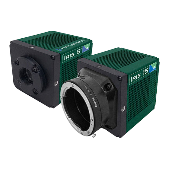
C-mount adapter for the Iris 9, or a standard F-mount adapter for the Iris 15. The camera also allows you to install any lens that is compatible with a either of these threaded video mounts if its optics do not extend behind the flange of the lens. -
Page 11: Chapter 2 - System Installation
Iris 9 and Iris 15 Scientific CMOS User Manual Chapter 2 – System Installation Carefully review the Precautions section in the previous chapter before performing any of the procedures outlined in this chapter. Again, use only a Iris Scientific CMOS PCI Express data cable and Iris PCI Express interface card with the camera. -
Page 12: Getting To Know Iris
To obtain the latest version of the library and drivers visit the Teledyne Photometrics website. The Teledyne Photometrics website also contains listings of third party software applications that support the Iris. -
Page 13: Host Computer Requirements
Windows-based computers. Additional instructions are included for installing a PCI Express interface card in the computer. The Teledyne Photometrics USB memory device contains the following files: • Manuals Directory — contains user manuals in PDF format. • Customer Case Studies — application examples •... - Page 14 Note: The model of PCIe card shipped with the camera may di er from the one shown in the photo. Warning: Do not use the PCIe interface supplied with the QImaging optiMOS Scientific CMOS camera with the Teledyne Photometrics Iris Scientific CMOS camera. While they have a common cable and connector, they are not compatible.
- Page 15 Iris 9 and Iris 15 Scientific CMOS User Manual Before attempting to operate the camera, first install this interface card into the PC with the following steps: 1. Shut down the PC 2. Unplug the PC from power mains and ensure the camera is turned o 3.
-
Page 16: Connecting Iris To Pci Express Bus
5. Camera is initialized and ready to communicate Tip: The power supply and connector used by the Iris Scientific CMOS camera is a common type. However, Teledyne Photometrics carefully selects power supplies for optimum noise performance, EMI compliance and stability. Do not swap power supplies with other lab equipment even though they may meet the connector, voltage and ampere requirements of the Iris. -
Page 17: Connecting Iris With Usb
A method for creating an independent root hub in computers with many USB devices is to install a PCI Express based USB3.0 interface card for use with the camera. In this case Teledyne Photometrics recommends using the PCIe interface described above, as it also provides improvements in maximum frame rate. -
Page 18: Chapter 3 - Theory Of Operation
Iris 9 and Iris 15 Scientific CMOS User Manual Chapter 3 – Theory of Operation Introduction Scientific CMOS sensors are quickly becoming the dominant sensor type in imaging technology. CMOS sensors are able to provide the highest levels of sensitivity due to the improved Quantum E ciency (QE) compared to CCD sensors. -
Page 19: Gain Combining And Bit-Depth
Iris 9 and Iris 15 Scientific CMOS User Manual Of course, there are many challenges to obtaining the same analog performance from each of the Iris’s nine (or fifteen) million pixels, whereas a CCD has a single, common output node resulting in a uniform response. The most... -
Page 20: Rolling And Global Shutter Readout
30.4 ms. Since readout and exposure are overlapped, the sensor achieves the maximum frame rate of 32fps with PCIe interface (Iris 9 and Iris 15) and 16fps for Iris 9 USB/ 10.5fps for Iris 15 USB). -
Page 21: Digital Binning
Iris 9 and Iris 15 Scientific CMOS User Manual Digital Binning Highlights of the Iris Scientific CMOS camera are shown below: CCD image sensors are capable of charge binning (combining adjacent pixels into one super pixel). This is accomplished as part of the charge transfer process and has the advantage of increasing signal to noise in read-noise limited situations, at the expense of spatial resolution. -
Page 22: Pixel Noise Filters
Iris 9 and Iris 15 Scientific CMOS User Manual Pixel Noise Filters Note: The Iris Scientific CMOS camera ships with an optimized default setting for Real Time Pixel Noise Filtering. Normally these values do not need to be adjusted. Additionally, the features described in this section may not be controllable in the software application. - Page 23 Programmable Gate Arrays) in order to provide new opportunities for extracting the best information from acquired images. Teledyne Photometrics has leveraged the revolution in computational imaging with many new capabilities. The Iris making computational imaging technology easy to deploy and accessible by embedding computational power inside the...
-
Page 24: Chapter 4 - Operating Features
Iris 9 and Iris 15 Scientific CMOS User Manual Chapter 4 – Operating Features Introduction This section explains Iris’s di erent modes of operation and the best modes to optimize imaging performance. Operating Frequencies Iris has a single pixel rate or speed: 480 Mpixels per second. System performance is optimized for this data rate, delivering the highest frame rates while maintaining the lowest noise, which delivers the best imaging quality. -
Page 25: Single And Multiple Regions Of Interest
Iris 9 and Iris 15 Scientific CMOS User Manual Tip: In some software applications, multiple clearing modes may be listed as they are required for other cameras, but when using Iris, be sure to only use “Clear Pre-Sequence”. For time-lapse acquisitions with a significant delay between frames, clearing before each exposure may be necessary to clear accumulated dark current. - Page 26 Iris 9 and Iris 15 Scientific CMOS User Manual - Line Delay When Programmable Scan Mode is set to Line Delay, a delay can be added after the line-time, slowing the propagation of the reset and readout signals. This causes the e ective line time of the sensor to be increased.
- Page 27 Iris 9 and Iris 15 Scientific CMOS User Manual Scan Width = Number of Rows between Reset and Readout When the Scan Width is set, the e ective line time required is automatically calculated. Exposure Time Line Time Effective Scan Width...
-
Page 28: Device Synchronization (Triggering)
Iris 9 and Iris 15 Scientific CMOS User Manual Device Synchronization Iris o ers several methods of integrating with external hardware devices. Each (Triggering) camera has four MMCX connectors on the back of the camera for trigger input/ output operations. The signals provided to the user are:... - Page 29 Iris 9 and Iris 15 Scientific CMOS User Manual Although “First Row” behavior provides the maximum camera frame rates, it does not avoid the overlap due to rolling shutter. This mode is not recommended if trying to alternate between excitation wavelengths.
- Page 30 Iris 9 and Iris 15 Scientific CMOS User Manual The following conditions may be defined for each expose out behavior: Rolling Shutter Rolling shutter mode takes all rows that have been taken simultaneously so as to capture an image at an instant. The expose out signal length is equal to the time between the start of the second row and the end of the first row’s exposure,...
-
Page 31: Smart Streaming
SMART Streaming Sequenced Multiple Acquisition Real Time Streaming, aka SMART Streaming, is an exclusive Teledyne Photometrics camera feature that enables Iris to capture a continuous sequence of images, while cycling through a maximum of 16 pre-programmed exposure time values. This avoids the overhead of host communication time, resulting in very high frame rate imaging while maintaining the correct exposure level for each fluorophore. -
Page 32: Chapter 5 - Troubleshooting
Chapter 5 – Troubleshooting For di culty in troubleshooting or if the symptoms are not listed here, contact Teledyne Photometrics Customer Service. System Does Not Boot If the operating system does not boot normally after the interface card is installed, Normally try reseating the PCIe card. -
Page 33: Images Not Displayed
(particularly the DATA and power cables), then restart. 4. Confirm the camera is operational by taking an image with a standard C-mount (Iris 9) / F-mount (Iris 15 ) lens attached to the camera. Using normal room lighting, place the camera on a table about three meters away from an object and acquire an image. -
Page 34: Chapter 6 - Basic Specifications
Sensor Process Microlens array Resolution (Iris 9) 2960 x 2960 (9 Megapixel) Resolution (Iris 15) 5056 x 2960 (15 Megapixel) Pixel Size (Iris 9) 4.25µm x 4.25µm Pixel size (Iris 15) 4.25µm x 4.25µm Digitization (Readout) Rate 480 MHz Power Supply Specifications... - Page 35 Iris 9 and Iris 15 Scientific CMOS User Manual www.photometrics.com Main Phone: +1 520.889.9933 Support: +1 604.530.5800 / +1 800.874.9789...
Need help?
Do you have a question about the Iris 15 and is the answer not in the manual?
Questions and answers