Advertisement
Quick Links
®
Bendix
BP-1
Brake Proportioning Valves
®
™
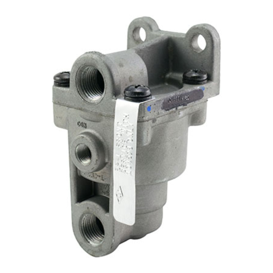
3/8 P.T.
SUPPLY PORT
1/8 P.T.
CONTROL PORT
3/8 P.T.
DELIVERY PORT
FIGURE 1 BP-1
BRAKE PROPORTIONING VALVES
™
DESCRIPTION OF THE BP-1
The BP-1
brake proportioning valves are incorporated into
™
the air brake systems to improve the controllability and
reduce the stopping distance of bobtail tractors during
braking. BP-1
™
, front and rear, valves reacting to the lack of
pressure in the trailer supply line reduce the braking effort
on the rear axles and increase the braking effort on the front
axle of tractors operating in the bobtail mode. Treadle
application force during bobtail operation resembles treadle
application force during normal operation with a connected
trailer.
A typical brake proportioning system is shown in Figure 6.
The system consists of a front and a rear brake proportioning
valve and a TR-3
valve.
™
Caution: The BP-1
front and BP-1
™
in appearance but are NOT interchangeable. Note
identification tag attached to one of the cover
screws (Figure 1); it will be stamped 'BP-1 Front'
VALVES
™
rear valves are similar
™
1.5
MOUNTING
PIECE NO.
STAMPED HERE
I.D. TAG STAMPED
BP-1 FRONT OR
BP-1 REAR
or 'BP-1 Rear'. The BP-1
without installing a BP-1
vehicle does not have a front axle ratio valve. If the
vehicle has a front axle ratio valve, the ratio valve
must be replaced with a BP-1
OPERATION
A tractor that is equipped with the BP-1
proportioning valve and TR-3
following manner. With the trailer supply valve pushed in
and a service brake application made, equal pressure (100%
of service application) will be delivered to each axle of the
tractor and trailer. When the trailer is disconnected from the
tractor and the trailer supply valve is pulled out, the front
axle of the tractor will receive 100% of the service brake
application pressure and the rear axle or axles approximately
25%. As application pressure increases, the differences
between the front axle and the rear axle(s) pressures
diminish.
.340"
HOLES (2)
rear valve can be used
™
front valve, providing the
™
™
front valve.
rear brake
™
™
valve only will respond in the
1
Advertisement

Related Manuals for BENDIX BP-1 BRAKE PROPORTIONING VALVES


Summary of Contents for BENDIX BP-1 BRAKE PROPORTIONING VALVES
- Page 1 ® Bendix BP-1 Brake Proportioning Valves ® ™ .340” MOUNTING HOLES (2) 3/8 P.T. SUPPLY PORT PIECE NO. STAMPED HERE I.D. TAG STAMPED BP-1 FRONT OR 1/8 P.T. BP-1 REAR CONTROL PORT 3/8 P.T. DELIVERY PORT FIGURE 1 BP-1 BRAKE PROPORTIONING VALVES ™...
- Page 2 A tractor that is equipped with both a front and rear axle brake proportioning valve with the trailer supply valve FULL DELIVERY MODE activated (tractor/trailer mode) will experience 50% of service (NO CONTROL PRESSURE) brake application pressure on the front axle up to 40 psi. With service applications above 40 psi the differential between the supply and delivery diminishes until at 60 psi it is a one-to-one ratio.
- Page 3 FIGURE 5 BP-1 FRONT BRAKE PROPORTIONING VALVE ™ system pressure has been depleted. CUTAWAY VIEW 8. Use only genuine Bendix ® replacement parts, delivers 50% of the service application to the actuators. components and kits. Replacement hardware, Service pressures above 40 psi begin to displace the upper tubing, hose, fittings, etc.
-
Page 4: Operational Checks
6. Remove the existing front axle ratio or limiting valve and 2. For vehicles equipped with a front axle service ratio or replace it with the BP-1 front valve. Connect the front ™ limiting valve (such as the Bendix LQ-4 valve) it must ® ™... -
Page 5: Preventive Maintenance
PREVENTIVE MAINTENANCE 2. Lubricate the six o-rings with the same material used in Step 1. Important: Review the Bendix Warranty Policy before performing any intrusive maintenance procedures. A warranty 3. Install the o-rings onto the pistons and the cover as shown may be voided if intrusive maintenance is performed during in Figure 4. - Page 6 2. Visually inspect all components for cracks, scoring, or instructions. damage of any kind. If any of these conditions exist, 11. Refer to section titled ‘Operational Checks’. the valve should be replaced. BW1554 © 2004 Bendix Commercial Vehicle Systems LLC All rights reserved. 3/2004 Printed in U.S.A.
Need help?
Do you have a question about the BP-1 BRAKE PROPORTIONING VALVES and is the answer not in the manual?
Questions and answers