Advertisement
Quick Links
®
Bendix
®
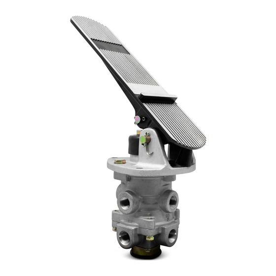
E-6
™
& E-10
BOOT
3/8" P.T.
PRIMARY
DELIVERY
3/8" P.T.
SECONDARY
DELIVERY
EXHAUST
™
FIGURE 1 - E-6
DUAL BRAKE VALVE
DESCRIPTION
™
The E-6
(Figure 1) and E-10
are floor mounted, treadle operated type brake valves with
two separate supply and delivery circuits for service (pri-
mary) and secondary braking, which provides the driver with
a graduated control for applying and releasing the vehicle
brakes.
™
The E-10
dual brake valve (Figure 2) is similar to the E-6
dual brake valve except that a metal coil spring housed in
an upper body assembly replaces the rubber spring used in
™
the E-6
valve. The use of a metal coil spring (and the upper
body assembly) provides greater treadle travel and, there-
fore, provides the driver with a less sensitive "feel" when
making a brake application. The E-10
generally used on buses, where smooth brake applications
contribute to passenger comfort.
™
The circuits in the E-6
/E-10
as follows: The primary circuit is that portion of the valve
between the spring seat which contacts the plunger and the
relay piston; the secondary circuit is that portion between
the relay piston and the exhaust cavity.
™
Dual Brake Valves
TREADLE
MOUNTING
PLATE
3/8" P.T.
PRIMARY
SUPPLY
3/8" P.T.
SECONDARY
SUPPLY
™
(Figure 2) dual brake valves
™
dual brake valve is
™
dual brake valves are identified
MOUNTING
PLATE
3/8" P.T.
PRIMARY
DELIVERY
3/8" P.T.
SECONDARY
DELIVERY
EXHAUST
™
FIGURE 2 - E-10
DUAL BRAKE VALVE
The primary circuit of the valve is similar in operation to a
standard single circuit air brake valve, and under normal
operating conditions the secondary circuit is similar in
operation to a relay valve.
Both primary and secondary circuits of the brake valve use
a common exhaust protected by an exhaust diaphragm.
™
OPERATION
APPLYING: NORMAL OPERATION - PRIMARY
CIRCUIT PORTION
When the brake treadle is depressed, the plunger exerts
force on the spring seat, graduating spring, and primary
piston. The primary piston, which contains the exhaust valve
seat, closes the primary exhaust valve. As the exhaust valve
closes, the primary inlet valve is moved off its seat allowing
primary air to flow out the primary delivery port.
TREADLE
3/8" P.T.
PRIMARY
SUPPLY
3/8" P.T.
SECONDARY
SUPPLY
1
Advertisement

Subscribe to Our Youtube Channel
Related Manuals for BENDIX E-10 DUAL BRAKE VALVES


Summary of Contents for BENDIX E-10 DUAL BRAKE VALVES
- Page 1 ® Bendix ® ™ & E-10 ™ Dual Brake Valves TREADLE TREADLE MOUNTING PLATE MOUNTING BOOT PLATE 3/8” P.T. PRIMARY 3/8” P.T. DELIVERY PRIMARY DELIVERY 3/8” P.T. 3/8” P.T. PRIMARY 3/8” P.T. SECONDARY 3/8” P.T. SUPPLY SECONDARY DELIVERY PRIMARY DELIVERY 3/8”...
- Page 2 FIGURE 4 - E-10 ™ DUAL BRAKE VALVE SECTIONAL FIGURE 3 - E-6 ™ DUAL BRAKE VALVE SECTIONAL DIAGRAM DIAGRAM APPLYING: NORMAL OPERATION - SECONDARY CIRCUIT delivery ports, the primary piston will mechanically move the relay piston, allowing the piston to close the secondary When the primary inlet valve is moved off its seat, air is exhaust valve and open the secondary inlet valve and allow permitted to pass through the bleed passage and enters the...
-
Page 3: Preventive Maintenance
Check the rubber plunger boot for cracks, holes or deterio- ration and replace if necessary. Also, check mounting plate and treadle for integrity. Apply a thin layer of Barium grease, per BW-204-M (Bendix part 246671), between plunger and mounting plate – do not over oil! MV-3 ™... -
Page 4: Leakage Check
50 pounds and care must be with a new or remanufactured unit, or repaired with genu- taken when removing the lock nut as the spring forces ine Bendix parts available at authorized Bendix parts will be released. It is recommended that the primary outlets. -
Page 5: Cleaning And Inspection
14. Install the lock nut (16) on the stem and torque to 20 - piston bores and metal to metal moving surfaces with Dow 30 inch pounds. Corning 55 M pneumatic grease (Bendix piece number 15. Install the primary piston retainer (15) over the piston, 291126). - Page 6 7. Never connect or disconnect a hose or line containing pressure; it may whip. Never remove a component or plug unless you are certain all system pressure has been depleted. 8. Use only genuine Bendix ® replacement parts, components and kits. Replacement hardware, tubing, hose, fittings, etc.
- Page 8 BW1427 © 2007 Bendix Commercial Vehicle Systems LLC. All rights reserved. 3/2007 Printed in U.S.A.
Need help?
Do you have a question about the E-10 DUAL BRAKE VALVES and is the answer not in the manual?
Questions and answers