Table of Contents
Advertisement
Quick Links
Operating Manual
Translation of the original operating manual
KBF-S ECO / KBF-S ECO-UL (E6)
Constant climate chambers with RD4 controller and Peltier technology
Model
KBF-S ECO 240
KBF-S ECO 240-UL
KBF-S ECO 400
KBF-S ECO 400-UL
KBF-S ECO 720
KBF-S ECO 720-UL
KBF-S ECO 1020
KBF-S ECO 1020-UL
BINDER GmbH
Address: Post office box 102, 78502 Tuttlingen, Germany Phone: +49 7462 2005 0
Fax: +49 7462 2005 100 Internet: http://www.binder-world.com
E-mail: info@binder-world.com Service Hotline: +49 7462 2005 555
Service Fax: +49 7462 2005 93 555 Service E-Mail: customerservice@binder-world.com
Service Hotline USA: +1 866 885 9794 or +1 631 224 4340 x3
Service Hotline Asia Pacific: +852 390 705 04 or +852 390 705 03
Service Hotline Russia and CIS: +7 495 988 15 16
Issue 07/2022
Model version
KBFSECO240-230V
KBFSECO240UL-120V
KBFSECO400-230V
KBFSECO400UL-120V
KBFSECO720-230V
KBFSECO720UL-120V
KBFSECO1020-230V
KBFSECO1020UL-120V
Art. No.
9020-0416, 9120-0416
9020-0420, 9120-0420
9020-0463, 9120-0463
9020-0464, 9120-0464
9020-0418, 9120-0418
9020-0421, 9120-0421
9020-0419, 9120-0419
9020-0422, 9120-0422
Art. No. 7001-0416
Advertisement
Table of Contents
Troubleshooting

Related Manuals for Binder KBF-S ECO 720-UL


Summary of Contents for Binder KBF-S ECO 720-UL
- Page 1 Fax: +49 7462 2005 100 Internet: http://www.binder-world.com E-mail: info@binder-world.com Service Hotline: +49 7462 2005 555 Service Fax: +49 7462 2005 93 555 Service E-Mail: customerservice@binder-world.com Service Hotline USA: +1 866 885 9794 or +1 631 224 4340 x3 ...
-
Page 2: Table Of Contents
Mounting the flexible tilt protection kit for chambers size 400 ............25 Water supply ............................. 26 4.3.1 Types of suitable water quality ....................26 4.3.2 BINDER Pure Aqua Service (option) ..................27 4.3.3 Installation of freshwater supply ..................... 27 Condensate collection pan ........................ 29 Electrical connection ......................... 30 FUNCTIONAL OVERVIEW OF THE RD4 CHAMBER CONTROLLER .... - Page 3 PASSWORD ......................37 Password request ..........................37 Assign and modify a password ......................38 9.2.1 Assign and modify the User password ................... 38 9.2.2 Assign and modify the Admin password ................. 38 10. TEMPERATURE SAFETY DEVICES ..............39 10.1 Over temperature protective device (class 1) ................... 39 10.2 Overtemperature safety controller class 3.1 ..................
- Page 4 23.2 Maintenance intervals, service ......................68 23.3 Service Reminder ..........................69 23.4 Simple troubleshooting ........................70 23.5 Sending the chamber back to BINDER GmbH ................. 72 24. DISPOSAL......................72 24.1 Disposal of the transport packing ...................... 72 24.2 Decommissioning ..........................73 24.3 Disposal of the chamber in the Federal Republic of Germany ............
-
Page 5: Safety
In no event shall BINDER be held liable for any damages, direct or incidental arising out of or related to the use of this manual. -
Page 6: Intellectual Property
35 U.S.C. § 287(a). Products and services listed on the BINDER website may be sold individually or as part of a combination product. Additional patent applications may also be pending in the U.S. -
Page 7: Safety Alert Symbol
NOTICE Indicates a potentially hazardous situation which, if not avoided, may result in damage to the product and/or its functions or of a property in its proximity. 1.4.2 Safety alert symbol Use of the safety alert symbol indicates a risk of injury. Observe all measures that are marked with the safety alert symbol in order to avoid death or in- jury. -
Page 8: Word Message Panel Structure
1.4.4 Word message panel structure Type / cause of hazard. Possible consequences. ∅ Instruction how to avoid the hazard: prohibition Instruction how to avoid the hazard: mandatory action. Observe all other notes and information not necessarily emphasized in the same way, in order to avoid disruptions that could result in direct or indirect injury or property damage. -
Page 9: Type Plate
Keep safety labels complete and legible. Replace safety labels that are no longer legible. Contact BINDER Service for these replacements. Type plate The type plate sticks to the left side of the chamber, bottom right-hand. Nominal temp. 70 °C 0,80 kW / 3,5 A Thermoelectric cooling 158 °F... -
Page 10: Ukca Label
(for Germany: DGUV guidelines 213-850 on safe working in laborato- ries, issued by the employers’ liability insurance association). BINDER GmbH is only responsible for the safety features of the chamber provided skilled electricians or qualified personnel authorized by BINDER perform all maintenance and repair, and if components relating to chamber safety are replaced in the event of failure with original spare parts. - Page 11 To operate the chamber, use only original BINDER accessories or accessories from third-party suppliers authorized by BINDER. The user is responsible for any risk caused by using unauthorized accessories. NOTICE Danger of overheating due to lack of ventilation. Damage to the chamber.
-
Page 12: Intended Use
Such ingredients include in particular acids and halides. Any corrosive damage caused by such ingredients is excluded from liability by BINDER GmbH. The chamber does not dispose of any measures of explosion protection. - Page 13 The requirements described in the Operating Manual for installation site and ambient conditions (Chap. 3.4) must be met. WARNING: If customer should use a BINDER chamber running in non-supervised continu- ous operation, we strongly recommend in case of inclusion of irrecoverable specimen or samples to split such specimen or samples and store them in at least two chambers, if this is feasible.
-
Page 14: Foreseeable Misuse
1.10 Foreseeable Misuse Other applications than those described in chap. 1.9 are not approved. This expressly includes the following misuses (the list is not exhaustive), which pose risks despite the in- herently safe construction and existing technical safety equipment: • Non-observance of Operating Manual •... - Page 15 • Absence of a plausibility check to rule out erroneous inscription of electrical components • Performance of repair work by untrained/insufficiently qualified personnel • Inappropriate repairs which do not meet the quality standard specified by BINDER • Use of replacement parts other than BINDER original replacement parts •...
-
Page 16: Operating Instructions
1.12 Operating instructions Depending on the application and location of the chamber, the operator of the chamber must provide the relevant information for safe operation of the chamber in a set of operating instructions. Keep these operating instructions with the chamber at all times in a place where they are clearly visible. -
Page 17: Resistance Of The Humidity Sensor Against Harmful Substances
1.14 Resistance of the humidity sensor against harmful substances The following list of harmful substances refers only to the humidity sensor and does not include any other materials incorporated in the chamber or prohibited substances in relation to explosion protection. Some gases –... -
Page 18: Chamber Description
A resistance humidifying system humidifies the air. For this purpose, use deionized (demineralized) water. The option BINDER Pure Aqua Service allows using the chamber with any degree of water hardness. Material: The inner chamber, the pre-heating chamber and the interior side of the doors are all made of stainless steel V2A (German material no. -
Page 19: Chamber Overview
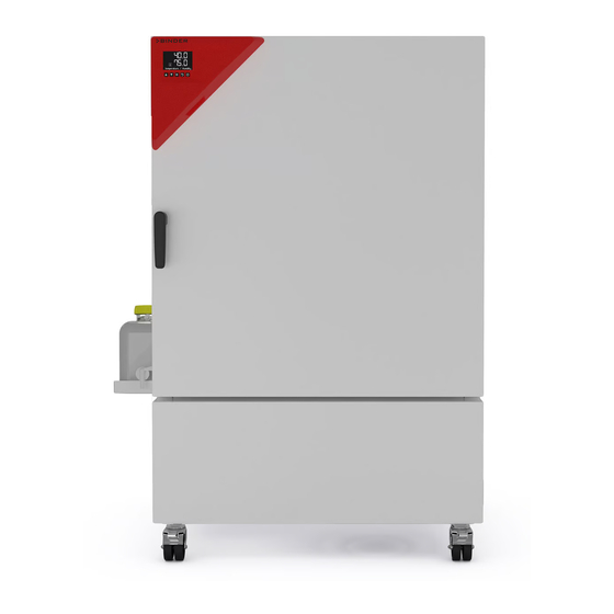
The chambers are equipped with four castors. Both front castors can be easily locked via the attached brakes. Temperature range: 0 °C / 32 °F up to 70 °C / 158 °F, humidity range: 20% r.h. to 80% r.h. For the control ranges of temperature and humidity, see climatic diagrams (chap. 19). Chamber overview Figure 6: Constant climate chamber KBF-S ECO / KBF-S ECO-UL size 240 Main power switch... -
Page 20: Rear Chamber View
Rear chamber view (10) (11) Figure 7: Rear view of the chamber (example: KBF-S ECO / KBF-S ECO-UL 720) Freshwater can with can support Hose leading to the freshwater can Hose fixing devices (10) Ethernet interface (11) Power cable KBF-S ECO / KBF-S ECO-UL (E6) 07/2022 Page 20/96... -
Page 21: Completeness Of Delivery, Transportation, Storage, And Installation
Note on second-hand chambers (Ex-Demo-Units): Second-hand chambers are chambers that were used for a short time for tests or exhibitions. They are thoroughly tested before resale. BINDER ensures that the chamber is technically sound and will work flaw- lessly. Second-hand chambers are marked with a sticker on the chamber door. Please remove the sticker before commissioning the chamber. -
Page 22: Storage
• If the steam humidifying system has NOT been emptied: +3 °C / 37.4 °F to +60 °C / 140 °F. • After BINDER Service has emptied the steam humidifying system: -10 °C / 14 °F to +60 °C / 140 °F. -
Page 23: Location Of Installation And Ambient Conditions
After extensive operation at humidity levels > 70% r.h., condensation from excessive humidity can lead to corrosion during storage. In this case the chamber must first be dried. NOTICE Danger of corrosion on the housing due to condensation by excess humidity after operating at humidity values >... - Page 24 Ambient conditions • Permissible ambient temperature range during operation: +18 °C / 64.4 °F to +32 °C / 89.6 °F. At ele- vated ambient temperature values, fluctuations in temperature can occur. The ambient temperature should not be substantially higher than the indicated ambient tem- perature of +22 °C +/- 3 °C / 71.6 °F +/- 5.4 °F to which the specified technical data relate.
-
Page 25: Installation And Connections
Installation and connections Spacers for wall distance Please fix both spacers with the supplied screws at the chamber rear. This serves to ensure the prescribed minimum distance to the wall of 100 mm / 3.94 in. Figure 8: Spacer for rear wall distance Figure 9: Rear chamber with mounted spacers Mounting the flexible tilt protection kit for chambers size 400 For chambers size 400, use the supplied flexible tilt protection kit in addition to the spacers for wall distance... -
Page 26: Water Supply
1 µS/cm (ultrapure water), may cause acid corrosion due to its low pH). • Tap water that has been treated by the optional water treatment system BINDER Pure Aqua Service (disposable system). A reusable measuring equipment to assess the water quality is included (chap. -
Page 27: Binder Pure Aqua Service (Option)
Water intake temperature NOT below +5 °C / 41 °F and not exceeding 40 °C / 104 °F. 4.3.2 BINDER Pure Aqua Service (option) The optional BINDER water treatment system (disposable system) is available to treat tap water. The life- time depends on water quality and the amount of treated water used. The measuring equipment to assess the water quality is reusable. - Page 28 Insert the freshwater can from above into the can support Insert the filled freshwater can from above into the can support. Figure 13: Freshwater can, placed in the can support on the left sidewall Mount the hose holders and fix the hose Mount the supplied hose holders at the provided points on the chamber rear and fix the hose to these hose holders in a way that it cannot bend.
-
Page 29: Condensate Collection Pan
The freshwater can outlet must NOT be placed on or above the rear panel or on the right sidewall of the chamber. DANGER Electrical hazard by water entering the chamber. Deadly electric shock. Damage to the chamber. Always place the freshwater can in the can support on the left side of the chamber. ∅... -
Page 30: Electrical Connection
• Only use original connection cables from BINDER according to the above specification. UL chambers: Use only a UL Listed Power supply cord (UL category ELBZ), SJT 3x14 AWG (2.08 mm²);... - Page 31 • Prior to connection and start-up, check the power supply voltage. Compare the values to the specified data located on the chamber’s type plate (left chamber side, bottom right-hand, see chap. 1.6). NOTICE Danger of incorrect power supply voltage due to improper connection. Damage to the chamber.
-
Page 32: Functional Overview Of The Rd4 Chamber Controller
“Set points” menu directly at the controller or use the APT-COM™ 4 Multi Management Software (option) specially developed by BINDER. The controller offers various notifications and alarm messages with visual and audible indication. All con- troller settings remain valid until the next manual change. They are stored also after turning off the chamber. -
Page 33: Menu Structure Of The Controller And Access Levels
• Admin: The password enables access to advanced controller functions and settings. Factory setting is 00 01. • Service: The password enables access to all controller functions (for BINDER Service only). As soon as a password has been assigned, access to the respective functions is blocked and only available after entering the correct password. -
Page 34: Performance During And After Power Failures
To reduce odors quickly we recommend heating up the chamber to its nominal temperature for one day and in a well-ventilated location. WARNING: If customer should use a BINDER chamber running in non-supervised continu- ous operation, we strongly recommend in case of inclusion of irrecoverable specimen or samples to split such specimen or samples and store them in at least two chambers, if this is feasible. -
Page 35: Temperature And Humidity Set-Point Entry
Temperature and humidity set-point entry Required access level: “User”. Setting ranges Control ranges 20 ºC below ambient temperature up to 70 °C / 158 °F -10 °C / 14 °F up to 70 °C / without humidity Temperature 158 °F. 10 °C / 50 °F up to 70 °C / 158 °F with humidity 20 % r.h. -
Page 36: Special Controller Functions - Turning Off The Humidity System, Idle Mode
Special controller functions – Turning off the humidity system, Idle mode Required access level: “User”. In the “Functions on/off” menu, you can define the switching state of two controller functions. Path: Normal display Setpoints Functions on/off • Function 1 “Humidity off” serves to turn off the humidification and dehumidification system Turning off humidity control in this menu is required when operating the chamber without water connec- tion in order to avoid humidity alarms. -
Page 37: Password
In Normal display the activated functions are shown. The “Info” icon flashes slowly. While it is lit, the lower text informs about the activated functions. Example: Normal display with activated function 1 “Humidity off” Temp. / Humidity Humidity off Password Password request To access menus for which access is restricted, you must enter the corresponding password. -
Page 38: Assign And Modify A Password
Assign and modify a password In this menu you can assign and modify the passwords of the “User” and “Admin” access levels. Required access level: “Admin”. Keep the password well in mind. There is no access to the corresponding menu functions without the correct password. -
Page 39: Temperature Safety Devices
The user cannot restart the device again. The protective cut-off device is located internally. Only a service specialist can replace it. Therefore, please contact an authorized service provider or BINDER Service. 10.2 Overtemperature safety controller class 3.1 The chambers are regularly equipped with an electronic overtemperature safety controller (temperature safety device class 3.1 according to DIN 12880:2007). -
Page 40: Setting The Safety Controller Mode
10.2.1 Setting the safety controller mode Required access level: “User”. Path: Normal display Setpoints Safety controller Mode Press the OK button to enable the setting. Setting the safety controller mode The current setting flashes. Use the arrow buttons to select between LIMI (Limit) and OFFS (Offset). -
Page 41: Message And Measures In The State Of Alarm
10.2.3 Message and measures in the state of alarm The state of alarm is indicated visually in Normal display. If the buzzer is enabled (chap. 13.3) there is an additional audible alert. The heating turns off. As soon as the inner chamber temperature has cooled down below the safety controller value, the heating is released and temperature control continues. -
Page 42: General Controller Settings
General controller settings The general settings can be accessed in the “Settings” submenu, which is available for users with “Service” or “Admin” authorization level. It serves to enter date and time, select the language for the controller menus and the desired temperature unit and to configure the controller’s communication functions. The display of some network settings is available for all users in the “Chamber info”... -
Page 43: Setting The Current Date
11.3 Setting the current date Required access level: “Admin”. Following start-up of the chamber (chap. 6), it is “User”. Path: Normal display Settings Chamber Date Press the OK button to enable the setting. Setting the date: day The current setting flashes. Enter the current day with the arrow but- tons. -
Page 44: Function "Language Selection At Restart
11.6 Setting the chamber address This setting is required for the communication with the BINDER APT-COM™ 4 Multi Management Software. The chamber address settings in the chamber controller and in the software must be identical. Required access level: “Admin”. -
Page 45: Display Brightness
11.7 Display brightness Required access level: “Admin”. Path: Normal display Settings Chamber Brightness Press the OK button to enable the setting. Setting the display brightness The current setting flashes. Enter the desired value with the arrow but- tons. Setting range: 10% up to 100% Confirm the entry with the OK button. -
Page 46: Setting The Temperature Tolerance Range
12.2 Setting the temperature tolerance range Normal display Settings Various Temperature range Path: Press the OK button to enable the setting. Setting the temperature tolerance range The current setting flashes. Enter the desired temperature range with the arrow buttons. Entry range: 1.0 °C up to 10.0 °C Confirm the entry with the OK button. -
Page 47: Notification And Alarm Functions
Notification and alarm functions 13.1 Information messages Information messages provide information about the settings made or the current controller condition. The message is displayed immediately when the condition occurs. In Normal display a text message indicates the condition. The “Information” icon is flashing slowly. -
Page 48: Alarm Messages
“<-<-< ” or “>->->” Safety controller sen- Safety controller temperature sensor defective immediately The humidity module is defective. Contact BINDER “Humidity system” immediately service The humidity module cannot fill up. Water can is empty or the tap is closed. Humidifica- tion turns off. -
Page 49: Activating / Deactivating The Audible Alarm (Alarm Buzzer)
Week programs: Programming is done using the BINDER RD4 Program Editor, which you can download from the BINDER website. The RD4 program editor is a Windows application that can be used to create programs on a PC and transfer them to compatible BINDER chambers via USB memory stick. -
Page 50: Start Week Program
Ethernet network settings The settings of this submenu are used for networking chambers with an Ethernet interface, e.g. to connect them with BINDER’s APT-COM™ 4 Multi Management Software (option, chap. 21.1). 15.1 Showing the network settings Required access level: “User”. -
Page 51: Showing The Chamber's Mac Address
15.1.1 Showing the chamber’s MAC address Path: Normal display Chamber info Ethernet MAC address Display of the MAC address (exam- ple) Toggle forth and back with the Back button and the OK button. 00:00:00:00:00:00 MAC address With the arrow-down button you can now change to the next parameter (IP address). With the Back button you can go back to the “Ethernet”... -
Page 52: Showing The Standard Gateway
15.1.4 Showing the standard gateway Path: Normal display Chamber info Ethernet Standard gateway Display of the standard gateway (example) Toggle forth and back with the Back button and the OK button. Standard gateway 0.0.0.0 With the arrow-down button you can now change to the next parameter (DNS server address). With the Back button you can go back to the “Ethernet”... -
Page 53: Changing The Configuration Of The Network Settings
15.2 Changing the configuration of the network settings Required access level: “Admin”. The “Ethernet” submenu offers to subsequently or individually access the following settings: • Selecting the type of assignment (automatic or manual) of the IP address, chap. 15.2.1 If automatic IP address assignment has been selected: •... -
Page 54: Assigning The Ip Address
With the Back button you can go back to the “Ethernet” submenu and, repeatedly pressing it, to Normal display. 15.2.3 Assigning the IP address Access to this function is possible only if manual IP address assignment has been selected (chap. 15.2.1) Path: Normal display Settings... -
Page 55: Setting The Subnet Mask
15.2.4 Setting the subnet mask Access to this function is possible only if manual IP address assignment has been selected (chap. 15.2.1) Path: Normal display Settings Ethernet Subnet mask Press the OK button to enable the setting. The subnet mask entry is done in four steps, corresponding to the number sections: (1).(2).(3).(4) Principle of entry: •... -
Page 56: Data Recorder
(chap. 16.3). Temperature values are always given out in °C. • Chamber data for BINDER Service “DL2” This data is intended for use by BINDER Service. It also contains information from the self-test function. The storage rate is fix (1 minute). Temperature values are always given out in °C. -
Page 57: Storage Capacity
16.4 Deleting the data recorder When importing a configuration via USB stick and when loading a new firmware version by BINDER service, the entire data memory is deleted. BINDER service can also install the configuration by means of a setup program without deleting the data. -
Page 58: Usb Menu: Data Transfer Via Usb Interface
For detailed information on the file content see chap. 16.1. • Service data The "Service" folder is created on the USB stick and can be sent to BINDER Service. In addition to the configuration and recorder data, it contains further service-relevant information. -
Page 59: Export Functions
17.3 Export functions Required access level: any user Function “Export configuration”. To write the configuration data from the controller to the USB stick, press the OK button. Export configuration With the arrow-down button you can now change to the next function. Function “Export recorder data”. -
Page 60: Removing The Usb Stick
The results of the self-test are stored in the service recorder of the controller. You can export them using the controller’s USB interface and send them to BINDER Service (use function “Export recorder data” to USB stick, chap. 17). BINDER Service will evaluate the data using an analyzing tool. -
Page 61: Deactivating The Self-Test Mode
Display showing the running self-test in Normal display (example values) Self-test active Do not open and do not turn off the chamber while self-test is running. After an interruption of the voltage supply, the self-test restarts. If desired, you can cancel an ongoing self-test by deactivating the self-test function in the controller menu (chap. -
Page 62: Humidification / Dehumidification System
Humidification / dehumidification system The chamber is equipped with a capacitive humidity sensor. This results in a control accuracy of up to +/- 3 % r.h. of the set point. The temperature-humidity diagrams (Figure 19) show the possible working ranges for humidity. -
Page 63: Function Of The Humidifying And Dehumidifying System
• Water intake temperature NOT below +5 °C / 41 °F and not exceeding 40 °C / 104 °F. BINDER GmbH is NOT responsible for the water quality provided by the customer. Any problems and malfunctions that might arise following use of water of deviating quality is excluded from liability by BINDER GmbH. -
Page 64: Defrosting At Refrigerating Operation
Options 21.1 APT-COM™ 4 Multi Management Software (option) The chamber is regularly equipped with an Ethernet interface (6) that can connect the BINDER APT-COM™ 4 Multi Management Software. The MAC Address is indicated in the “Ethernet” controller menu (chap. 15.1.1). The actual temperature and humidity values are given at adjustable intervals. Programming can be performed graphically via PC. -
Page 65: Cleaning And Decontamination
Do not use cleaning agents that may cause a hazard due to reaction with components of the device or the charging material. If there is doubt regarding the suitability of cleaning products, please contact BINDER service. We recommend using the neutral cleaning agent Art. No. 1002-0016 for a thorough cleaning. -
Page 66: Decontamination / Chemical Disinfection
Do not use decontamination agents that may cause a hazard due to reaction with components of the device or the charging material. If there is doubt regarding the suitability of cleaning products, please contact BINDER service. KBF-S ECO / KBF-S ECO-UL (E6) 07/2022... - Page 67 For chemical disinfection, we recommend using the disinfectant spray Art. No. 1002-0022. Any corrosive damage that may arise following use of other disinfectants is excluded from lia- bility by BINDER GmbH. With every decontamination method, always use adequate personal safety controls.
-
Page 68: Maintenance And Service, Troubleshooting, Repair, Testing
For personnel requirements please refer to the Service Manual. • Repair Repair of the chamber can be performed by BINDER Service or by BINDER qualified service partners or technicians, in accordance with the description in the Service Manual. After maintenance, the chamber must be tested prior to resuming operation. -
Page 69: Service Reminder
With an increased amount of dust in the ambient air, clean the Peltier fan grid (by suction or blowing) several times a year. We recommend taking out a maintenance agreement. Please consult BINDER Service: BINDER telephone hotline: +49 (0) 7462 2005 555... -
Page 70: Simple Troubleshooting
If there are is a technical fault or shortcoming, take the chamber out of operation and inform BINDER Service. If you are not sure whether there is a technical fault, proceed ac- cording to the following list. If you cannot clearly identify an error or there is a technical fault, please contact BINDER Service. - Page 71 Humidity fluctuation, together with temperature fluctuation > Select cooler place of installation Place of installation too hot. 1 °C with a set-point approx. 3 °C or contact BINDER service. above ambient temperature. Peltier module for dehumidifica- Contact BINDER service. tion defective.
-
Page 72: Sending The Chamber Back To Binder Gmbh
23.5 Sending the chamber back to BINDER GmbH If you return a BINDER product to us for repair or any other reason, we will only accept the product upon presentation of an authorization number (RMA number) that has previously been issued to you. An au- thorization number will be issued after receiving your complaint either in writing or by telephone prior to your sending the BINDER product back to us. -
Page 73: Decommissioning
(Elektro- und Elektronikgerätegesetz, ElektroG from 20 October 2015, BGBl. I p. 1739) or contact BINDER service who will organize taking back and disposal of the cham- ber according to the German national law for electrical and electronic equipment (Elektro- und El- ektronikgerätegesetz, ElektroG from 20 October 2015, BGBl. -
Page 74: Disposal Of The Chamber In The Member States Of The Eu Except For The Federal Republic Of Germany
According to Annex I of Directive 2012/19/EU of the European Parliament and of the Council on waste electrical and electronic equipment (WEEE), BINDER devices are classified as “monitoring and control instruments” (category 9) only intended for professional use”. They must not be disposed of at public col- lecting points. -
Page 75: Disposal Of The Chamber In Non-Member States Of The Eu
Danger of violation against existing law if not disposed of properly. Failure to comply with applicable law. Alteration of the environment. For final decommissioning and disposal of the chamber, please contact BINDER ser- vice. Follow the statutory regulations for appropriate, environmentally friendly disposal. -
Page 76: Technical Description
(certified since December 1996 by TÜV CERT). All test equipment used is subject to the administration of measurement and test equipment that is also a constituent part of the BINDER QM DIN EN ISO 9001 systems. They are controlled and calibrated to a DKD-Standard at regular intervals. -
Page 77: Kbf-S Eco / Kbf-S Eco-Ul Technical Data
25.4 KBF-S ECO / KBF-S ECO-UL technical data Chamber size 1020 Exterior dimensions Width, gross (incl. access port) mm / inch 932 / 36.69 932 / 36.69 1255 / 49.37 1255 / 49.37 Width, gross (incl. can support) mm / inch 1108 / 43.62 1108 / 43.62 1432 / 56.38 1432 / 56.38 Height, gross (incl. - Page 78 +22 °C +/- 3°C / 71.6 °F +/- 5.4 °F and a power supply voltage fluctuation of +/-10%. Technical data is determined in accordance to BINDER Factory Standard Part 2:2015 and DIN 12880:2007. All indications are average values, typical for chambers produced in series. We reserve the right to change technical specifications at any time.
-
Page 79: Equipment And Options (Extract)
25.5 Equipment and options (extract) To operate the chamber, use only original BINDER accessories or accessories / components from third-party suppliers authorized by BINDER. The user is responsible for any risk arising from using unauthorized accessories. Regular equipment... -
Page 80: Accessories And Spare Parts (Extract)
25.6 Accessories and spare parts (extract) BINDER GmbH is responsible for the safety features of the chamber only, provided skilled electricians or qualified personnel authorized by BINDER perform all maintenance and repair, and if components relating to chamber safety are replaced in the event of failure with original spare parts. -
Page 81: Dimensions
25.7 Dimensions Dimensions size 240: [mm] KBF-S ECO / KBF-S ECO-UL (E6) 07/2022 Page 81/96... - Page 82 Dimensions size 400: [mm] KBF-S ECO / KBF-S ECO-UL (E6) 07/2022 Page 82/96...
- Page 83 Dimensions size 720: [mm] KBF-S ECO / KBF-S ECO-UL (E6) 07/2022 Page 83/96...
- Page 84 Dimensions size 1020: [mm] KBF-S ECO / KBF-S ECO-UL (E6) 07/2022 Page 84/96...
-
Page 85: Certificates And Declarations Of Conformity
Certificates and declarations of conformity 26.1 EU Declaration of Conformity KBF-S ECO / KBF-S ECO-UL (E6) 07/2022 Page 85/96... - Page 86 KBF-S ECO / KBF-S ECO-UL (E6) 07/2022 Page 86/96...
- Page 87 KBF-S ECO / KBF-S ECO-UL (E6) 07/2022 Page 87/96...
-
Page 88: Ukca Declaration Of Conformity
26.2 UKCA Declaration of Conformity KBF-S ECO / KBF-S ECO-UL (E6) 07/2022 Page 88/96... -
Page 89: Certificate For The Gs Mark Of Conformity Of The "Deutsche Gesetzliche Unfallversicherung E.v." (German Social Accident Insurance) Dguv
26.3 Certificate for the GS mark of conformity of the “Deutsche Gesetzliche Unfallversicherung e.V.” (German Social Accident Insurance) DGUV KBF-S ECO / KBF-S ECO-UL (E6) 07/2022 Page 89/96... - Page 90 KBF-S ECO / KBF-S ECO-UL (E6) 07/2022 Page 90/96...
-
Page 91: Contamination Clearance Certificate
Contamination clearance certificate 27.1 For chambers located outside USA and Canada Declaration regarding safety and health Erklärung zur Sicherheit und gesundheitlichen Unbedenklichkeit The German Ordinance on Hazardous Substances (GefStofV), and the regulations regarding safety at the workplace, require that this form be filled out for all products that are returned to us, so that the safety and the health of our employees can be guaranteed Die Sicherheit und Gesundheit unserer Mitarbeiter, die Gefahrstoffverordnung GefStofV und die Vorschriften zur Si- cherheit am Arbeitsplatz machen es erforderlich, dass dieses Formblatt für alle Produkte, die an uns zurückgeschickt... - Page 92 Kind of transport / transporter / Transportweg/Spediteur: Transport by (means and name of transport company, etc.) Versendung durch (Name Spediteur o.ä.) ___________________________________________________________________________________ Date of dispatch to BINDER GmbH / Tag der Absendung an BINDER GmbH ___________________________________________________________________________________ KBF-S ECO / KBF-S ECO-UL (E6) 07/2022 Page 92/96...
- Page 93 We hereby commit ourselves and guarantee that we will indemnify BINDER GmbH for all damages that are a consequence of incomplete or incorrect information provided by us, and that we will exempt BINDER GmbH from eventual damage claims by third parties / Wir versichern, dass wir gegenüber BINDER für jeden...
-
Page 94: For Chambers Located In Usa And Canada
Please complete this form and the Customer Decontamination Declaration (next 2 pages) and attach the required pictures. E-mail to: IDL_SalesOrderProcessing_USA@binder-world.com After we have received and reviewed the complete information we will decide on the issue of a RMA num- ber. Please be aware that size specifications, voltage specifications as well as performance specifications are available on the internet at www.binder-world.us... - Page 95 Customer (End User) Decontamination Declaration Health and Hazard Safety declaration To protect the health of our employees and the safety at the workplace, we require that this form is com- pleted by the user for all products and parts that are returned to us. (Distributors or Service Organizations cannot sign this form) NO RMA number will be issued without a completed form.
- Page 96 4.5 Shipping laws and regulations have not been violated. I hereby commit and guarantee that we will indemnify BINDER Inc. for all damages that are a con- sequence of incomplete or incorrect information provided by us, and that we will indemnify and hold harmless BINDER Inc.
Need help?
Do you have a question about the KBF-S ECO 720-UL and is the answer not in the manual?
Questions and answers