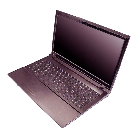
Summarization of Contents
Chapter 1: Introduction
Overview
Provides a general overview of the manual's scope and content.
Specifications
Details the technical specifications of the notebook computer models.
External Locator - Top View
Identifies external components on the top view of the notebook.
External Locator - Front & Right Side Views
Identifies external components on the front and right side views.
External Locator - Left Side & Rear View
Identifies external components on the left side and rear views.
External Locator - Bottom View
Identifies external components on the bottom view of the notebook.
Mainboard Overview - Top (Key Parts)
Highlights key components on the top side of the mainboard.
Mainboard Overview - Bottom (Key Parts)
Highlights key components on the bottom side of the mainboard.
Mainboard Overview - Top (Connectors)
Identifies connectors on the top side of the mainboard.
Mainboard Overview - Bottom (Connectors)
Identifies connectors on the bottom side of the mainboard.
Chapter 2: Disassembly
Overview
Introduces step-by-step instructions for disassembling notebook parts and subsystems.
Maintenance Tools
Lists recommended tools for performing repairs and maintenance on the notebook.
Connections
Describes the four types of internal computer connections.
Maintenance Precautions
Outlines safety precautions to prevent injury and computer damage during service.
Cleaning
Provides instructions for safely cleaning the notebook computer.
Disassembly Steps
Lists the disassembly procedures and corresponding page references.
Removing the Battery
Step-by-step guide for safely removing the notebook battery.
Removing the Hard Disk Drive
Instructions for removing and upgrading the notebook's hard disk drive.
Removing the Optical Device
Guide on how to remove the notebook's CD/DVD drive.
Removing the System Memory (RAM)
Instructions for removing and replacing the system memory modules.
Removing and Installing a Processor
Detailed procedure for removing and installing the CPU.
Removing the Wireless LAN Module
Step-by-step instructions to remove the wireless LAN module.
Removing the Keyboard
Procedure for safely removing and reinstalling the notebook keyboard.
Appendix A: Part Lists
Part List Illustration Location
Table indicating where to find specific part list illustrations.
Top (W251HU/W252HU/W255HU SERIES)
Part list illustration for the top assembly of specific notebook series.
Top (W258HU SERIES)
Part list illustration for the top assembly of the W258HU series.
Bottom
Part list illustration for the bottom assembly of the notebook.
Combo
Part list illustration for the optical drive combo module.
DVD
Part list illustration for the DVD drive component.
LCD (W25X HUQ)
Part list illustration for the LCD assembly of W25X HUQ models.
LCD (W25X HUM)
Part list illustration for the LCD assembly of W25X HUM models.
Appendix B: Schematic Diagrams
System Block Diagram
Provides a high-level overview of the notebook's system architecture.
CPU 1/7 (DMI, PEG, FDI)
Detailed schematic of CPU interfaces including DMI, PEG, and FDI.
CPU 2/7 (CLK, MISC, JTAG)
Schematic detailing CPU clock, MISC, and JTAG signals.
DDR3 SO-DIMM_0
Schematic diagram for the DDR3 SO-DIMM slot A.
LVDS, Inverter
Schematic for the LVDS interface and LCD inverter circuitry.
HDMI, CRT
Schematic diagrams for HDMI and CRT display output ports.
Power 1.5V/0.75V/1.8VS
Schematics detailing power supply circuits for 1.5V, 0.75V, and 1.8VS.
Power V-Core1
Schematic for the V-Core1 power supply regulation.
Charger, DC In
Schematic diagram for the DC power input and battery charging circuitry.
Appendix C: Updating the FLASH ROM BIOS
Download the BIOS
Instructions on how to download the correct BIOS version from the manufacturer's website.
Unzip Files to Bootable Media
Guide on preparing a bootable CD/DVD/USB with BIOS files.
Set Boot Order in BIOS
Steps to configure the BIOS to boot from external media.
Update BIOS using Flash Tools
Procedure for using flash tools to update the system's BIOS.
Restart and Configure BIOS
Instructions for restarting the system and loading default BIOS settings.


Need help?
Do you have a question about the W255HU and is the answer not in the manual?
Questions and answers