
Related Manuals for Miller Blue Star185DX


Summary of Contents for Miller Blue Star185DX
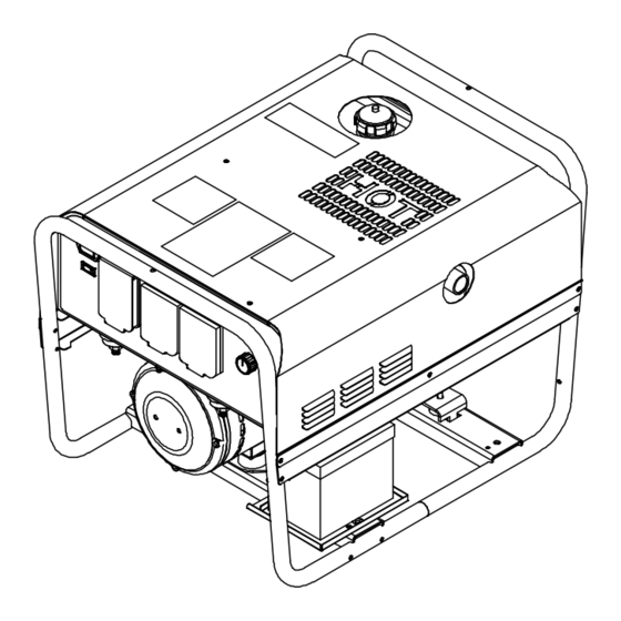
- Page 1 OM-248 551D 2012−06 Processes Stick (SMAW) Welding Description Engine Driven Welding Generator Blue Star 145DX, 185DX File: Engine Drive Visit our website at www.MillerWelds.com...
- Page 2 We know you don’t have time to do it any other way. That’s why when Niels Miller first started building arc welders in 1929, he made sure his products offered long-lasting value and superior quality.
-
Page 3: Table Of Contents
TABLE OF CONTENTS SECTION 1 − SAFETY PRECAUTIONS − READ BEFORE USING ....... . 1-1. - Page 4 TABLE OF CONTENTS SECTION 10 − PARTS LIST ..............10-1.
-
Page 5: Section 1 − Safety Precautions − Read Before Using
SECTION 1 − SAFETY PRECAUTIONS − READ BEFORE USING rom_2011−10 Protect yourself and others from injury — read, follow, and save these important safety precautions and operating instructions. 1-1. Symbol Usage DANGER! − Indicates a hazardous situation which, if Indicates special instructions. not avoided, will result in death or serious injury. - Page 6 D Do not weld on containers that have held combustibles, or on FUMES AND GASES can be hazardous. closed containers such as tanks, drums, or pipes unless they are properly prepared according to AWS F4.1 and AWS A6.0 (see Welding produces fumes and gases. Breathing these Safety Standards).
-
Page 7: Engine Hazards
1-3. Engine Hazards EXHAUST SPARKS can cause fire. BATTERY EXPLOSION can injure. D Do not let engine exhaust sparks cause fire. D Always wear a face shield, rubber gloves, and protective clothing when working on a battery. D Use approved engine exhaust spark arrestor in required areas —... -
Page 8: Additional Symbols For Installation, Operation, And Maintenance
HOT METAL from air arc cutting and MOVING PARTS can injure. gouging can cause fire or explosion. D Keep away from moving parts such as fans, D Do not cut or gouge near flammables. belts and rotors. D Watch for fire; keep extinguisher nearby. D Keep all doors, panels, covers, and guards closed and securely in place. - Page 9 BATTERY CHARGING OUTPUT and BATTERY STATIC (ESD) can damage PC boards. EXPLOSION can injure. D Put on grounded wrist strap BEFORE handling Battery charging not present on all models. boards or parts. D Use proper static-proof bags and boxes to D Always wear a face shield, rubber gloves, and protective store, move, or ship PC boards.
-
Page 10: California Proposition 65 Warnings
1-6. California Proposition 65 Warnings For Gasoline Engines: Welding or cutting equipment produces fumes or gases which contain chemicals known to the State of California to Engine exhaust contains chemicals known to the State of cause birth defects and, in some cases, cancer. (California California to cause cancer, birth defects, or other reproduc- Health &... -
Page 11: Section 2 − Consignes De Sécurité − Lire Avant Utilisation
SECTION 2 CONSIGNES DE SÉCURITÉ − LIRE AVANT − UTILISATION fre_rom_2011−10 Pour écarter les risques de blessure pour vous−même et pour autrui — lire, appliquer et ranger en lieu sûr ces consignes relatives aux précautions de sécurité et au mode opératoire. 2-1. - Page 12 Il reste une TENSION DC NON NÉGLIGEABLE dans les LES RAYONS DE L’ARC peuvent sources de soudage onduleur UNE FOIS le moteur coupé. provoquer des brûlures dans les yeux et sur la peau. D Couper l’alimentation du poste et décharger les condensateurs d’entrée comme indiqué...
-
Page 13: Dangers Existant En Relation Avec Le Moteur
D Protéger les bouteilles de gaz comprimé d’une chaleur excessive, LE BRUIT peut affecter l’ouïe. des chocs mécaniques, des dommages physiques, du laitier, des flammes ouvertes, des étincelles et des arcs. Le bruit des processus et des équipements peut D Placer les bouteilles debout en les fixant dans un support station- affecter l’ouïe. -
Page 14: Dangers Liés À L'air Comprimé
LA VAPEUR ET LE LIQUIDE DE L’ACIDE DE LA BATTERIE peut pro- REFROIDISSEMENT CHAUD peuvent voquer des brûlures dans les YEUX et provoquer des brûlures. sur la PEAU. D Il est préférable de vérifier le liquide de refroi- D Ne pas renverser la batterie. dissement une fois le moteur refroidi pour éviter D Remplacer une batterie endommagée. -
Page 15: Dangers Supplémentaires En Relation Avec L'installation, Le Fonctionnement Et La Maintenance
détendre la pression et s’assurer que le circuit d’air ne peut être L’INHALATION D’AIR COMPRIMÉ risque mis sous pression par inadvertance. de provoquer des blessures ou même D Demander seulement à un personnel qualifié d’enlever la mort. les dispositifs de sécurité ou les recouvrements pour effectuer, s’il y a lieu, des travaux d’entretien et de dépannage. - Page 16 LA SORTIE DE RECHARGE et L’EXPLO- LES CHARGES ÉLECTROSTATI- SION BATTERIE peuvent QUES peuvent endommager les provoquer des blessures. circuits imprimés. D Établir la connexion avec la barrette de terre La recharge de batterie n’existe pas sur tous les avant de manipuler des cartes ou des pièces. modèles.
-
Page 17: Proposition Californienne 65 Avertissements
2-6. Proposition californienne 65 Avertissements Pour les moteurs à essence : Les équipements de soudage et de coupage produisent des fumées et des gaz qui contiennent des produits chimiques Les gaz d’échappement des moteurs contiennent des pro- dont l’État de Californie reconnaît qu’ils provoquent des mal- duits chimiques dont l’État de Californie reconnaît qu’ils formations congénitales et, dans certains cas, des cancers. -
Page 18: Section 3 − Definitions
Complete Parts List available at www.MillerWelds.com SECTION 3 − DEFINITIONS 3-1. Symbol Definitions Read Operator’s Engine Choke Amperes Volts Manual Engine Oil Fuel Battery (Engine) Engine Alternating Current Positive Negative Output (AC) Protective Earth Hours Seconds Time (Ground) Circuit Protector Temperature SECTION 4 −... -
Page 19: Dimensions, Weights, And Operating Angles
Complete Parts List available at www.MillerWelds.com 4-3. Dimensions, Weights, And Operating Angles Dimensions Height 22-3/4 in (578 mm) Width 22-3/4 in (577 mm) Depth 31-5/8 in (803 mm) Do not exceed tilt angles or engine could be damaged or unit could tip. 31-5/8 in (803 mm) Do not move or operate unit where it 10-9/16 in (268 mm) -
Page 20: Volt-Ampere Curves
Complete Parts List available at www.MillerWelds.com 4-5. Volt-Ampere Curves The volt-ampere curve shows the minimum and maximum voltage and amperage output capabilities of the welding generator. Curves of all other settings fall between the curves shown. A. 145 Model AMPERES 220 602 B. -
Page 21: Fuel Consumption
Complete Parts List available at www.MillerWelds.com 4-6. Fuel Consumption A. Fuel Consumption While Welding 1.00 0.80 185 Model 0.60 0.40 145 Model 0.20 Idle 0.00 DC Weld Amperes At Rated Duty Cycle B. Fuel Consumption − Auxiliary Power 1.00 185 Model 0.80 0.60 145 Model... -
Page 22: Generator Power Curve
Complete Parts List available at www.MillerWelds.com 4-7. Generator Power Curve The ac generator power curves show the generator power available in amperes at the receptacles. 145 Model generator output is ap- proximately 85% of 185 Model shown. 240 VOLT 120 VOLT AMPERES 220 594−A Notes... -
Page 23: Section 5 − Installation
Complete Parts List available at www.MillerWelds.com SECTION 5 − INSTALLATION 5-1. Installing Welding Generator Movement Airflow Clearance 18 in. (460 mm) 18 in. 18 in. (460 mm) (460 mm) 18 in. 18 in. (460 mm) (460 mm) Location Do not install unit where air flow is restricted or engine may overheat. -
Page 24: Grounding Generator When Supplying Building Systems
Complete Parts List available at www.MillerWelds.com 5-3. Grounding Generator When Supplying Building Systems Ground generator to sys- tem earth ground if supply- GND/PE ing power to a premises (home, shop, farm) wiring system. Equipment Grounding Terminal Grounding Cable Use #8 AWG or larger insulated copper wire. -
Page 25: Engine Prestart Checks
Complete Parts List available at www.MillerWelds.com 5-5. Engine Prestart Checks Check all fluids daily. Engine must be cold and on a level surface. Unit is shipped with 10W30 engine oil. Fuel Valve Open valve. Close fuel valve before moving unit or carburetor may flood and make starting difficult. -
Page 26: Connecting The Battery
Complete Parts List available at www.MillerWelds.com 5-6. Connecting The Battery Turn Engine Switch to Off. Connect negative (−) cable last. − Tools Needed: 1/2 in. 803 595-B / 803 466 5-7. Weld Output Terminals Negative (−) Weld Output Terminal Positive (+) Weld Output Terminal For Direct Current Electrode Posi- tive (DCEP), connect work cable to... -
Page 27: Connecting To Weld Output Terminals
**Weld cable size (AWG) is based on either a 4 volts or less drop or a current density of at least 300 circular mils per ampere. ( ) = mm for metric use ***For distances longer than those shown in this guide, call a factory applications rep. at 920-735-4505 (Miller) or 1-800-332-3281 (Hobart). Ref. S-0007-J 2011−07 OM-248 551 Page 23... -
Page 28: Section 6 − Operating The Welding Generator
Complete Parts List available at www.MillerWelds.com SECTION 6 − OPERATING THE WELDING GENERATOR 6-1. Engine Controls Engine Switch Choke Control D Electric-Start: Turn Engine switch to Start position. Use switch to control ignition circuit. Turn Use control to change engine air/fuel mix. Recoil: Turn Engine switch to On posi- switch to Start position for electric start. -
Page 29: Front Panel Controls
Complete Parts List available at www.MillerWelds.com 6-2. Front Panel Controls 218 610 Welding Range Table Weld Output Control plate. Adjust control to obtain desired weld performance. Use table to determine correct weld amper- Set control at maximum for full generator EXAMPLE: age based on electrode size, type, and mate- power output at AC receptacles. -
Page 30: Section 7 − Operating Auxiliary Equipment
Complete Parts List available at www.MillerWelds.com SECTION 7 − OPERATING AUXILIARY EQUIPMENT 7-1. Generator Power Panel Receptacles 145 Model 185 Model 4.5 kVa/kW Peak 6 kVa/kW Peak 4 kVa/kW Continuous 5.5 kVa/kW Continuous 34/17 Amperes 40/23 Amperes 120/240 Volts AC 120/240 Volts AC 60 Hz 60 Hz... -
Page 31: Gfci Receptacle Information, Resetting And Testing
Complete Parts List available at www.MillerWelds.com 7-2. GFCI Receptacle Information, Resetting And Testing Test and reset GFCI only at Run speed and with controls set for full generator power. RotGFCI2 2012−05 Use GFCI protection when operat- A GFCI receptacle does not protect against controls at Max to achieve full generator ing auxiliary equipment. -
Page 32: Section 8 − Maintenance
Complete Parts List available at www.MillerWelds.com SECTION 8 − MAINTENANCE Follow the storage procedure in the engine owner’s manual if the unit will not be used for an extended period. 8-1. Routine Maintenance Stop engine before maintaining. See Engine Manual and Maintenance Label Recycle engine for important start-up, service, and storage fluids. -
Page 33: Maintenance Label
Complete Parts List available at www.MillerWelds.com 8-2. Maintenance Label Ref. 258 079 OM-248 551 Page 29... -
Page 34: Servicing Air Cleaner
Complete Parts List available at www.MillerWelds.com 8-3. Servicing Air Cleaner Stop engine. Let cool NOTICE − Do not run engine with- out air cleaner element or with dirty element. Screw Foam Element Inspect foam element. If element is damaged, replace. If element is clogged, wash foam element with soap and water solution. -
Page 35: Adjusting Engine Speed
Complete Parts List available at www.MillerWelds.com 8-6. Adjusting Engine Speed After tuning engine, check engine speed. See engine maintenance label for proper no load speed. If necessary, adjust speed as follows: Start engine and run until warm. Set Weld Output Control to Max. Weld/Power Speed Adjustment Adjustment Screw To increase speed, turn screw in... -
Page 36: Section 9 − Troubleshooting
Complete Parts List available at www.MillerWelds.com SECTION 9 − TROUBLESHOOTING 9-1. Troubleshooting A. Welding Trouble Remedy No weld output or generator power out- Be sure all equipment is disconnected from receptacles when starting unit. put at ac receptacles. Have Factory Authorized Service Agent check brushes, slip rings, rotor, stator, integrated rectifier SR2, and Weld Output control R1. -
Page 37: Section 10 − Parts List
Complete Parts List available at www.MillerWelds.com Trouble Remedy Erratic output at generator power ac Check fuel level. receptacles. Have Factory Authorized Service Agent check connections at terminal block 1T. Check receptacle supplementary protector, wiring, and connections. Check throttle linkage for smooth, non-binding operation. Service air cleaner according to engine manual. - Page 38 Complete Parts List available at www.MillerWelds.com Notes OM-248 551 Page 34...
-
Page 39: Section 11 − Electrical Diagrams
SECTION 11 − ELECTRICAL DIAGRAMS 226 738-C Figure 11-1. Circuit Diagram for Welding Generator OM-248 551 Page 35... -
Page 40: Section 12 − Generator Power Guidelines
SECTION 12 − GENERATOR POWER GUIDELINES The views in this section are intended to be representative of all engine-driven welding generators. Your unit may differ from those shown. 12-1. Selecting Equipment Generator Power Receptacles − Neutral Bonded To Frame 3-Prong Plug From Case Grounded Equipment 2-Prong Plug From Double Insulated Equipment... - Page 41 12-3. Grounding When Supplying Building Systems Equipment Grounding Terminal Grounding Cable Use #8 AWG or larger insulated copper wire. GND/PE Ground Device Use ground device as stated in electrical codes. Ground generator to system earth ground if supplying power to a premises (home, shop, farm) wiring system.
- Page 42 12-5. Approximate Power Requirements For Industrial Motors Industrial Motors Rating Starting Watts Running Watts Split Phase 1/8 HP 1/6 HP 1225 1/4 HP 1600 1/3 HP 2100 1/2 HP 3175 Capacitor Start-Induction Run 1/3 HP 2020 1/2 HP 3075 3/4 HP 4500 1400 1 HP...
- Page 43 12-7. Approximate Power Requirements For Contractor Equipment Contractor Rating Starting Watts Running Watts Hand Drill 1/4 in. 3/8 in. 1/2 in. Circular Saw 6-1/2 in. 7-1/4 in. 8-1/4 in. 1400 1400 Table Saw 9 in. 4500 1500 10 in. 6300 1800 Band Saw 14 in.
- Page 44 12-8. Power Required To Start Motor Single-Phase Induction Motor Starting Requirements Motor Start Code KVA/HP 10.0 11.2 12.5 14.0 Motor Start Code Running Amperage Motor HP Motor Voltage To find starting amperage: Step 1: Find code and use table to find kVA/HP.
- Page 45 12-10. Typical Connections To Supply Standby Power Have only qualified persons perform these connections according to all applicable codes and safety practices. Properly install, ground, and operate this equipment ac- cording to its Owner’s Manu- Fused Welding Utility al and national, state, and lo- Disconnect Electrical Generator...
- Page 46 12-11. Selecting Extension Cord (Use Shortest Cord Possible) Cord Lengths for 120 Volt Loads Use GFCI protection when operating auxiliary equipment. If unit does not have GFCI receptacles, use GFCI-protected exten- sion cord. Do not use GFCI receptacles to power life support equipment. Maximum Allowable Cord Length in ft (m) for Conductor Size (AWG)* Current Load (Watts)
-
Page 47: Section 13 − Stick Welding (Smaw) Guidelines
SECTION 13 − STICK WELDING (SMAW) GUIDELINES 13-1. Stick Welding Procedure Weld current starts when electrode touches work- piece. Equipment Needed: Tools Needed: Weld current can damage electronic parts in vehicles. Disconnect both battery cables before welding on a vehicle. Place work clamp as close to the weld as possible. - Page 48 13-2. Electrode and Amperage Selection Chart 6010 DEEP 3/32 MIN. PREP, ROUGH HIGH SPATTER 6011 DEEP 6010 5/32 & 6013 EP,EN GENERAL 3/16 6011 7/32 SMOOTH, EASY, 7014 EP,EN FAST 1/16 LOW HYDROGEN, 7018 5/64 STRONG 3/32 FLAT SMOOTH, EASY, 7024 EP,EN HORIZ...
- Page 49 13-4. Positioning Electrode Holder End View Of Work Angle Side View Of Electrode Angle ° ° ° ° Groove Welds ° ° ° ° Fillet Welds S-0060 13-5. Poor Weld Bead Characteristics Large Spatter Deposits Rough, Uneven Bead Slight Crater During Welding Bad Overlap Poor Penetration S-0053-A...
- Page 50 13-7. Conditions That Affect Weld Bead Shape Weld bead shape is affected electrode angle, length, travel speed, and thick- ness of base metal. Correct Angle ° - ° Angle Too Large Angle Too Small Electrode Angle Drag Spatter Arc Length Normal Too Long Too Short...
- Page 51 13-9. Groove (Butt) Joints Tack Welds Prevent edges of joint from draw- ing together ahead of electrode by tack welding the materials in posi- tion before final weld. Square Groove Weld Good for materials up to 3/16 in. (5 mm) thick. Single V-Groove Weld Good for materials 3/16 −...
- Page 52 13-12. Weld Test Vise Weld Joint Hammer Strike weld joint in direction shown. A good weld bends over but does not break. 2 To 3 in. (51-76 mm) 2 To 3 in. (51-76 mm) 1/4 in. (6.4 mm) S-0057-B 13-13. Troubleshooting Porosity −...
- Page 53 Lack Of Penetration − shallow fusion between weld metal and base metal. Lack of Penetration Good Penetration Possible Causes Corrective Actions Improper joint preparation. Material too thick. Joint preparation and design must provide access to bottom of groove. Improper weld technique. Keep arc on leading edge of weld puddle.
- Page 54 Notes Ref. AWS/ANSI D1.1 WELD JOINT TYPES GROOVE FILLET WELD POSITION: FLAT BUTT T−JOINT HORIZONTAL BUTT T−JOINT VERTICAL BUTT T−JOINT OVERHEAD BUTT T−JOINT Ref. 804 248-A OM-248 551 Page 50...
- Page 55 Effective January 1, 2012 (Equipment with a serial number preface of MC or newer) This limited warranty supersedes all previous Miller warranties and is exclusive with no other Warranty Questions? guarantees or warranties expressed or implied. LIMITED WARRANTY − Subject to the terms and conditions 90 Days —...
- Page 56 Contact the Delivering Carrier to: File a claim for loss or damage during shipment. For assistance in filing or settling claims, contact your distributor and/or equipment manufacturer’s Transportation Department. © ORIGINAL INSTRUCTIONS − PRINTED IN USA 2012 Miller Electric Mfg. Co. 2012−01...
Need help?
Do you have a question about the Blue Star185DX and is the answer not in the manual?
Questions and answers