Table of Contents
Advertisement
Quick Links
Advertisement
Table of Contents
Troubleshooting

Related Manuals for Miller Maxstar 300 SD


Summary of Contents for Miller Maxstar 300 SD
- Page 1 OM-2222 189 533L September 2001 Processes TIG (GTAW) Welding Stick (SMAW) Welding Description 230/460 Volt Models W/AutolinkR 400 Volts Models Arc Welding Power Source Maxstar 300 SD, DX And LX And Non-CE Models Visit our website at www.MillerWelds.com...
- Page 2 – every power source from This Owner’s Manual is designed to help you get the most out of your Miller is backed by the most Miller products. Please take time to read the Safety precautions. They will hassle-free warranty in the business.
- Page 3 TABLE OF CONTENTS SECTION 1 – SAFETY PRECAUTIONS - READ BEFORE USING ......1-1.
-
Page 4: Table Of Contents
TABLE OF CONTENTS SECTION 5 – MAINTENANCE AND TROUBLESHOOTING ....... . . 5-1. - Page 5 Declaration of Conformity For European Community (CE) Products NOTE This information is provided for units with CE certification (see rating label on unit.) Miller Electric Mfg. Co. Manufacturer’s Name: 1635 W. Spencer Street Manufacturer’s Address: Appleton, WI 54914 USA Maxstar...
- Page 7 SECTION 1 – SAFETY PRECAUTIONS - READ BEFORE USING som _nd_4/98 1-1. Symbol Usage Means Warning! Watch Out! There are possible hazards with this procedure! The possible hazards are shown in the adjoining symbols. This group of symbols means Warning! Watch Out! possible Y Marks a special safety message.
- Page 8 ARC RAYS can burn eyes and skin. BUILDUP OF GAS can injure or kill. D Shut off shielding gas supply when not in use. Arc rays from the welding process produce intense D Always ventilate confined spaces or use visible and invisible (ultraviolet and infrared) rays that can burn eyes and skin.
- Page 9 1-3. Additional Symbols For Installation, Operation, And Maintenance FIRE OR EXPLOSION hazard. MOVING PARTS can cause injury. D Do not install or place unit on, over, or near D Keep away from moving parts such as fans. combustible surfaces. D Keep all doors, panels, covers, and guards D Do not install unit near flammables.
- Page 10 1-5. EMF Information Considerations About Welding And The Effects Of Low Frequency 1. Keep cables close together by twisting or taping them. Electric And Magnetic Fields 2. Arrange cables to one side and away from the operator. Welding current, as it flows through welding cables, will cause electro- magnetic fields.
- Page 11 SECTION 1 – CONSIGNES DE SECURITE – LIRE AVANT UTILISATION som _nd_fre 4/98 1-1. Signification des symboles Signifie Mise en garde ! Soyez vigilant ! Cette procédure présente des risques de danger ! Ceux-ci sont identifiés par des symboles adjacents aux directives. Ce groupe de symboles signifie Mise en garde ! Soyez vigilant ! Il y a des Y Identifie un message de sécurité...
- Page 12 LES RAYONS DE L’ARC peuvent pro- LES ACCUMULATIONS DE GAZ ris- voquer des brûlures dans les yeux et quent de provoquer des blessures ou sur la peau. même la mort. Le rayonnement de l’arc du procédé de soudage D Fermer l’alimentation du gaz protecteur en cas de génère des rayons visibles et invisibles intenses non utilisation.
- Page 13 1-3. Dangers supplémentaires en relation avec l’installation, le fonctionnement et la maintenance Risque D’INCENDIE OU DES ORGANES MOBILES peuvent D’EXPLOSION. provoquer des blessures. D Ne pas placer l’appareil sur, au-dessus ou à proxi- D Rester à l’écart des organes mobiles comme le mité...
- Page 14 1-4. Principales normes de sécurité Safety in Welding and Cutting, norme ANSI Z49.1, de l’American Wel- Safe Handling of Compressed Gases in Cylinders, CGA Pamphlet P-1, ding Society, 550 N.W. Lejeune Rd, Miami FL 33126 de la Compressed Gas Association, 1235 Jefferson Davis Highway, Suite 501, Arlington, VA 22202.
- Page 15 SECTION 2 – DEFINITIONS (CE Models Only) 2-1. Warning Label Definitions Warning! Watch Out! There are possible hazards as shown by the symbols. Electric shock from welding electrode or wiring can kill. 1.1 Wear dry insulating gloves. Do not touch electrode with bare hand.
- Page 16 Warning! Watch Out! There are possible hazards as shown by the symbols. Electric shock from wiring can kill. Disconnect input plug or power before working on machine. Hazardous voltage remains on input capacitors after power is turned off. Do not touch fully charged capacitors.
- Page 17 2-2. Manufacturer’s Rating Label For CE Products Only For label location see Section 3-4. ST-188 153-A OM-2222 Page 11...
- Page 18 2-3. Symbols And Definitions Gas Tungsten Arc Shielded Metal Arc Amperes Panel–Local Welding (GTAW) Welding (SMAW) 3 Phase Static Frequency Volts Input Converter-Transformer-Rectifier Output Circuit Breaker Remote Lift-Arc (GTAW) Protective Earth Postflow Timer Preflow Timer Seconds (Ground) Positive Negative Alternating Rated Welding Gas Input Gas Output...
- Page 19 SECTION 3 – INSTALLATION 3-1. Specifications A. For Multivoltage Units Amperes Input At Welding Max. Rated Output, 60Hz Input Rated Output at Amperage Amperage Open-Circuit Open-Circuit Dimensions Dimensions Power 60% Duty Cycle Weight Range Voltage 82 lb Three- 250 A @ 30 VDC, 25.4 16.2 12.8...
- Page 20 3-3. Duty Cycle And Overheating Duty Cycle is the percentage of 10 minutes that unit can weld at rated load without overheating. If unit overheats, output stops, a Help message is displayed (see Section 5-3), and cooling fan runs. Wait fifteen minutes for unit to cool. Reduce amperage or voltage, or duty cycle before welding.
- Page 21 3-4. Selecting A Location Lifting Handles Use handles to lift unit. Hand Cart Dimensions And Weight Use cart or similar device to move 82 lb (37 kg) – 100 lb (45 kg) w/aux power 24 in unit. (610 mm) Rating Label (Non CE Models) Use rating label to determine input power needs.
- Page 22 3-5. 115 Volts AC Duplex Receptacle, Circuit breaker (Optional) And Power Switch AC Duplex Receptacle 115 V 10 A for 230/460 volt models. 115 V 7 A for 400 volt models. Circuit Breaker CB1 CB1 protects duplex receptacle from overload. Press button to reset breaker.
- Page 23 3-7. Remote 14 Receptacle Information Socket* Socket Information Contactor control 24 volts dc. 24 VOLTS DC 24 VOLTS DC C L N OUTPUT Contact closure to A completes 24 volts dc CONTACTOR contactor control circuit and enables output. Output to remote control; 0 to +10 volts dc output to remote control.
- Page 24 3-8. Remote Program Select Inputs (Optional For DX Models) 10-Pin Receptacle RC2 Pin Designations 0 = No Connection / 1 = Connected To Ground (Pin G) X= Do Not Care Function No Remote Control Stick EP Of Current Program Program 1 Stick EP Program 2 Stick EP Program 3 Stick EP Program 4 Stick EP...
- Page 25 3-9. Automation Connection (LX Models) Socket Socket Information For 10-Pin Receptacle RC2 Start/Stop Output Disable Chassis ground Final slope – collector Final slope – emitter Pulse lockout – collector Pulse lockout – emitter ST-802 137-A ST-802 137-A Valid arc – collector Valid arc –...
- Page 26 3-10. Gas Connections Gas Fitting Fittings have 5/8-18 right-hand threads. Cylinder Valve Open valve slightly so gas flow blows dirt from valve. Close valve. Regulator/Flowmeter Flow Adjust Typical flow rate is 15 cfh (cubic feet per hour). Connect customer supplied gas hose between regulator/flowmeter and gas fitting on rear of unit.
- Page 27 3-12. Front Panel Display For TIG HF Impulse DCEN (Direct Current Electrode Negative) Front Panel Correct front panel display for basic TIG HF Impulse DCEN welding. For all front panel switch pad controls: press switch pad to turn on light and enable function.
- Page 28 3-13. Stick DCEP (Direct Current Electrode Positive) Connections Negative (–) Weld Output Terminal Connect work lead to negative weld output terminal. Positive (+) Weld Output Terminal Connect electrode holder to posi- tive weld output terminal. Remote 14 Receptacle If desired, connect remote control to Remote 14 receptacle (see Sec- tion 3-7).
- Page 29 3-14. Front Panel Display For Stick DCEP (Direct Current Electrode Positive) Front Panel Correct front panel display for basic Stick DCEP welding. For all front panel switch pad controls: press switch pad to turn on light and enable function. NOTE: Gray on nameplate indi- cates a Stick function (see Section 4-1 for description of controls).
- Page 30 3-15. Electrical Service Guide A. For Multivoltage Units Actual input voltage cannot exceed ± 10% of indicated required input voltage. If NOTE actual input voltage is outside of this range, no output is available. Three-Phase Single-Phase Input Voltage Input Amperes At Rated Output 15.8 40.2 Max Recommended Standard Fuse Or Circuit Breaker Rating In Amperes...
- Page 31 3-16. Connecting Input Power Y Disconnect and lockout/tag- out input power before con- necting input conductors from unit. Y Have only qualified persons make this installation. Check input voltage available at site. Line Disconnect Device Input And Grounding Conductors See Section 3-15. Green Or Green/Yellow For three-phase opera-...
- Page 32 SECTION 4 – OPERATION 4-1. Controls A. Non CE Units (DX/LX Models Shown) Rear Panel Voltmeter Adjust Controls For all front panel switch pad controls: press See Section 4-3. See Section 4-8. switch pad to turn on light and enable Process Controls function.
- Page 33 B. For CE Units (DX/LX Models Shown) Rear Panel Voltmeter Adjust Controls For all front panel switch pad controls: press See Section 4-3. See Section 4-8. switch pad to turn on light and enable Process Controls function. Power Switch See Section 4-4. NOTE: Green on nameplate indicates a TIG Use switch to turn unit On/Off.
- Page 34 4-2. Encoder Control Encoder Control Use control in conjunction with ap- plicable front panel function switch pad to set values for that function. 4-3. Ammeter And Volt Meter Volt Meter Displays output or open circuit volt- age. If output is off, the voltmeter will display a series of three dashes (-––).
- Page 35 4-5. Lift-Arc And HF TIG Start Procedures Lift-Arc Start When Lift-Arct button light is On, start arc as follows: TIG Electrode Workpiece Touch tungsten electrode to work- piece at weld start point, enable out- put with torch trigger, foot control, or hand control.
- Page 36 4-6. Output Control CE Models Only Output Control welding power source, initial amps, source. initial slope, final slope, and final amps Press switch pad until desired param- NOTE: If On/Off only type trigger is are not functional. eter LED is illuminated. used, it must be a maintained switch.
- Page 37 Output Control welding power source. Press switch pad until desired parameter NOTE: Switch function can be reconfi- Press switch pad to activate function. LED is illuminated. gured for 4T, 4TE, Mini Logic, or Spot con- Output is available when LED is illumi- trol (see Section 4-13).
- Page 38 4-7. Amperage Control A (Amperage Control) Encoder Control Ammeter Press Amperage switch pad, and turn Encoder control to set weld amperage (5-300 amps). Weld am- perage setting is also peak amper- age when Pulser function is active (see Section 4-9). Amperage se- lected is displayed on ammeter (see Section 4-3) and the ammeter A LED will be illuminated.
- Page 39 4-8. Adjust Controls (Preflow, Post Flow, DIG) Preflow/Post Flow/DIG Control Press switch pad until desired func- tion LED is illuminated. Encoder Control Ammeter Preflow - If the TIG process is ac- tive (see Section 4-4), press switch pad and turn encoder control to set length of time (0–15 seconds) gas flows before arc initiation.
- Page 40 4-9. Pulser Control (DX And LX Models) Pulser Control Press switch pad to enable pulser. Press switch pad until desired pa- rameter LED is illuminated. Pulsing is available only while using the TIG process, it cannot be selected if the Stick process (see Section 4-4) is active.
- Page 41 4-10. Sequencer Controls (DX, LX And All CE Models) Sequencer Control Press switch pad until desired pa- rameter LED is illuminated. Se- quencing is available only while us- ing the TIG process, but is disabled if a remote foot or finger current control is connected to the Remote receptacle (see Section 3-7).
- Page 42 4-11. Memory (Program Storage Locations 1-4) (DX And LX Models) Memory (Program Storage 1-4) Switch Pad Process Switch Pad Each program storage location, 1–4, is capable of storing two weld- ing parameter programs, one for TIG (TIG HF Impulse or TIG Lift Arc), and one for Stick.
- Page 43 Notes OM-2222 Page 37...
- Page 44 4-12. Programmable TIG HF Impulse Start Amperage And Time Modes Accessing Programmable TIG Start Amperage And Time Modes (All Models) Non CE Models Only Rear Panel NOTE: Before accessing programmable Process And Amperage Key Pads 7 seconds (or until software version num- TIG HF Impulse Start Amperage and Time ber _ _ _ _ _ _-_clears meters).
- Page 45 CE Models Only Rear Panel NOTE: Before accessing programmable Process And Amperage Key Pads 7 seconds (or until software version number TIG HF Impulse Start Amperage and Time _ _ _ _ _ _-_clears meters). Power Switch modes, be sure that all procedures and pa- rameters are established.
- Page 46 Setting Programmable TIG Impulse Start Amperage (All Models) Non CE Models Only NOTE: Before accessing programmable mode. and pulser functions are active, their re- TIG HF Impulse Start Amperage mode, be spective LEDs will be illuminated. Amperage Switch Pad sure that all procedures and parameters The “30 ”...
- Page 47 CE Models Only NOTE: Before accessing programmable mode. and pulser functions are active, their re- TIG Impulse Start Amperage mode, be spective LEDs will be illuminated. Amperage Control sure that all procedures and parameters The “30 ” displayed on the amps meter is are established.
- Page 48 C. Setting Programmable Start Time (All Models) Non CE Models Only NOTE: Before accessing programmable programmable start mode, but program pa- Press Amperage switch pad. Switch pad start time mode, be sure that all procedures rameters cannot be adjusted while in this LED turns on, meter S LED turns on, and and parameters are established.
- Page 49 CE Models Only NOTE: Before accessing programmable programmable start mode, but program pa- Press Amperage switch pad. Switch pad start time mode, be sure that all procedures rameters cannot be adjusted while in this LED turns on, meter S LED turns on, and and parameters are established.
- Page 50 4-13. Reconfiguring 2T For 4T, 4T Momentary, Mini Logic Control, Or Spot (DX, LX And All CE Models) Non CE Models Only Rear Panel Process Switch Pad Encoder Control tion required to reconfigure for Mini Logic. Use Encoder to change functions. Ac- Output Switch Pad tive function will be displayed on am- Proceed to Section 4-15 for 4T Mo-...
- Page 51 (See Section 4-6 for operation) (See Section 4-14 for operation) Mini Logic (See Section 4-15 for operation) 4T Momentary (See Section 4-17 for operation) Spot (See Section 4-16 for operation) OM-2222 Page 45...
- Page 52 Reconfiguring 2T For 4T, 4T Momentary, Mini Logic Control, Or Spot (DX, LX And All CE Models) (Continued) CE Models Only Rear Panel Process Switch Pad Encoder Control tion required to reconfigure for Mini Logic. Use Encoder to change functions. Ac- Output Switch Pad tive function will be displayed on am- Proceed to Section 4-15 for 4T Mo-...
- Page 53 (See Section 4-6 for operation) (See Section 4-14 for operation) = Mini Logic (See Section 4-15 for operation) 4T Momentary (See Section 4-17 for operation) Spot (See Section 4-16 for operation) OM-2222 Page 47...
- Page 54 4-14. 4T Specific Trigger Method (DX, LX And All CE Models) 4T (Specific Trigger Operation) Sequencer is required to reconfi- gure for 4T. Select 4T according to Section 4-13. Torch trigger operation is as shown. = 4T While in 4T mode, there is a func- tion available during the main weld sequence that allows the operator to toggle between weld current and...
- Page 55 4-15. Mini Logic Operation (DX, LX And All CE Models) Mini Logic Meter Display Sequencer option required to re- configure for Mini Logic. Select Mini Logic according to Sec- tion 4-13. Torch trigger operation is as shown. Mini Logic During Mini Logic welding opera- tion, the weld current can be toggled between the initial amps level and the main weld amps level...
- Page 56 4-16. Spot Control Operation (All Models) Spot Function Meter Display Select Spot function according to Section 4-13. Amperage Switch Pad Encoder Control Set spot parameters as follows: Press Amperage switch pad once Spot (meter A LED turns on) and turn En- coder to set spot amperage.
- Page 57 4-17. 4T Momentary Operation (DX, LX And All CE Models) 4T Momentary Meter Display Select 4T Momentary according to Section 4-13. If unit is equipped with Sequence Controls, a 4T Momentary trigger method is available. 4T Momentary torch trigger op- eration is as shown.
- Page 58 4-18. Arc Timer/Counter Display (All Models) Non CE Models 123 456 Rear Panel Output And Amperage Controls Arc Timer Display Arc Counter Upon power up as described, the meter S After 5 seconds, the meter A LED turns Power Switch LED will turn on, and arc time will be dis- on, and the arc counter will be displayed played for 5 seconds as [000 000 ] to [999...
- Page 59 CE Models 123 456 Rear Panel Output And Amperage Controls Arc Timer Display Arc Counter Upon power up as described above, the After 5 seconds, the meter A LED turns Power Switch meter S LED will turn on, and arc time on, and the arc counter will be displayed To display the arc timer/counter, turn will be displayed for 5 seconds as [000...
- Page 60 4-19. Lockout Functions A. Accessing Lockout Capability L - - or 2,3,4 L L1 Rear Panel See Section 4-1 for explanation of controls referred to in all of Toggle Amperage (A) switch pad to light the meter S LED. You may Section 4-19.
- Page 61 B. Lockout Levels Level 1 Level 1 NOTE: Before activating lockout levels, be sure that all procedures and parameters are established. Parameter adjustment is limited while lockout levels are active. NOTE: Remote amperage control is not available in level 1. TIG Output Selection If either the TIG Impulse HF or TIG Lift Arc process (see Section 4-6)
- Page 62 C. Lock Out Levels (Continued) Level 3 Level 3 NOTE: Before activating lockout levels, be sure that all procedures and parameters are established. Pa- Use Encoder Control To rameter adjustment is limited while Adjust Amperage +/– 10% lockout levels are active. Of Preset Value.
- Page 63 4-20. Resetting Unit To Factory Default Settings Process Switch Pad Output Switch Pad Adjust Switch Pad Power Switch To reset all welding power source functions to original factory settings, turn power off. Push and hold the Process, Output and Adjust switch pads and turn On power switch.
-
Page 64: Section 5 - Maintenance And Troubleshooting
SECTION 5 – MAINTENANCE AND TROUBLESHOOTING 5-1. Routine Maintenance Y Disconnect power before maintaining. Maintain more often during severe conditions. 3 Months Replace Clean and tighten Replace Damaged unreadable weld terminals. Gas Hose labels. 3 Months Repair Or Replace Cracked Cables And Cords 6 Months Y Do not remove case when... -
Page 65: Voltmeter/Ammeter Help Displays
5-3. Voltmeter/Ammeter Help Displays HE.L HE.L HE.L HE.L HE.L HE.L HE.L HE.L HE.L HE.L HE.L HE.L HE.L Help 4 Display display is shown. Can also be displayed if All directions are in reference to the the board power supply is being shorted. Indicates an open in the thermal protection front of the unit. -
Page 66: Troubleshooting
5-4. Troubleshooting Trouble Remedy No weld output; unit completely Place line disconnect switch in On position (see Section 3-16). inoperative. Check and replace line fuse(s), if necessary, or reset circuit breaker (see Section 3-16). Check for proper input power connections (see Section 3-16). No weld output;... - Page 67 Notes OM-2222 Page 61...
-
Page 68: Section 6 - Electrical Diagrams
SECTION 6 – ELECTRICAL DIAGRAMS Figure 6-1. Circuit Diagram OM-2222 Page 62... - Page 69 200 325-A OM-2222 Page 63...
-
Page 70: Section 7 - High Frequency
SECTION 7 – HIGH FREQUENCY 7-1. Welding Processes Requiring High Frequency High-Frequency Voltage TIG – helps arc jump air gap between torch and workpiece and/ or stabilize the arc. Work high_freq 12/96 – S-0693 7-2. Incorrect Installation Weld Zone 11, 12 50 ft (15 m) Sources of Direct High-Frequency... -
Page 71: Correct Installation
7-3. Correct Installation Weld Zone 50 ft (15 m) 50 ft (15 m) Ground all metal ob- jects and all wiring in welding zone using #12 AWG wire. Ground workpiece if required by codes. Nonmetal Building Metal Building Ref. S-0695 / Ref. S-0695 High-Frequency Source (welding Conduit Joint Bonding and Grounding Metal Building Requirements... -
Page 72: Section 8 - Selecting And Preparing
SECTION 8 – SELECTING AND PREPARING TUNGSTEN ELECTRODE gtaw 7/97 NOTE For additional information, see your distributor for a handbook on the Gas Tungsten Arc Welding (GTAW) process. Wear clean gloves to prevent contamination of tungsten electrode. 8-1. Selecting Tungsten Electrode ♦... -
Page 73: Preparing Tungsten For Dc Electrode Negative (Dcen) Welding
8-3. Preparing Tungsten For DC Electrode Negative (DCEN) Welding Tungsten Electrode Tapered End Grind end of tungsten on fine grit, hard abrasive wheel before weld- ing. Do not use wheel for other jobs or tungsten can become contami- nated causing lower weld quality. 2-1/2 Times Electrode Diameter Stable Arc... -
Page 74: Section 9 - Guidelines For Tig Welding (Gtaw)
SECTION 9 – GUIDELINES FOR TIG WELDING (GTAW) 9-1. Positioning The Torch Y Grinding the tungsten elec- trode produces dust and fly- ing sparks which can cause injury and start fires. Use lo- cal exhaust (forced ventila- tion) at the grinder or wear an approved respirator. -
Page 75: Torch Movement During Welding
9-2. Torch Movement During Welding Tungsten Without Filler Rod ° Welding direction Form pool Tilt torch Move torch to front of pool. Repeat process. Tungsten With Filler Rod ° ° Welding direction Form pool Tilt torch Add filler metal Remove rod Move torch to front of pool. -
Page 76: Positioning Torch Tungsten For Various Weld Joints
9-3. Positioning Torch Tungsten For Various Weld Joints ° Butt Weld And Stringer Bead ° ° ° “T” Joint ° ° ° ° Lap Joint ° ° ° ° Corner Joint ° ° ST-162 003 / S-0792 OM-2222 Page 70... - Page 77 Notes OM-2222 Page 71...
-
Page 78: Section 10 - Parts List
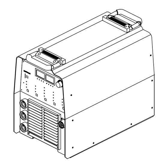
SECTION 10 – PARTS LIST Hardware is common and not available unless listed. Figure 10-1. Main Assembly ST-802 005-G OM-2222 Page 72... - Page 79 Quantity Model Item Dia. Part 230/460 400 CE Mkgs. Description Figure 10-1. Main Assembly ....195 585 HANDLE, rubberized carrying .......
- Page 80 Quantity Model Item Dia. Part 230/460 400 CE Mkgs. Description Figure 10-1. Main Assembly (Continued) ... 191 181 CONNECTOR & SOCKETS 10-pin (LX Models) ....
- Page 81 Hardware is common and not available unless listed. ST-802 006-D Figure 10-2. Windtunnels w/Components Quantity Model Item Dia. Part 230/460 400 CE Mkgs. Description Figure 10-2. Windtunnels w/Components (Fig 10-1 Item 39) ..
- Page 82 Quantity Model Item Dia. Part 230/460 400 CE Mkgs. Description Figure 10-2. Windtunnels w/Components (Fig 10-1 Item 39) (Continued) ....025 248 STAND-OFF, insul .250-20 x 1.250 lg .
- Page 83 Effective January 1, 2000 (Equipment with a serial number preface of “LA” or newer) This limited warranty supersedes all previous Miller warranties and is exclusive with no other Warranty Questions? guarantees or warranties expressed or implied. Call LIMITED WARRANTY – Subject to the terms and conditions APT, ZIPCUT &...
-
Page 84: Options And Accessories
Distributor Address City State For Service Call 1-800-4-A-Miller or see our website at www.MillerWelds.com to locate a DISTRIBUTOR or SERVICE AGENCY near you. Always provide Model Name and Serial/Style Number. Contact your Distributor for: Welding Supplies and Consumables Options and Accessories...
Need help?
Do you have a question about the Maxstar 300 SD and is the answer not in the manual?
Questions and answers