Table of Contents
Advertisement
Quick Links
V8200A,C,H,M and VR8200A,C,H,M
Continuous Pilot Combination Gas
Controls
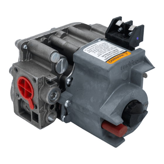
APPLICATION
These continuous pilot combination gas controls are
used in gas-fired appliances up to 200 cfh capacity of
natural gas. They include safety shutoff, a manual valve,
one or two automatic operators, a pressure regulator
and a pilot filter. Body pattern is straight-through with
1/2 in. inlet and 1/2 in. outlet. An ECO connector (part
no. 393200-1) with two 1/4 in. quick connect terminals
is available.
See Table 1 for model differences and Table 2 for
temperature ranges and regulator types.
Additional 90° angle and straight flanges are available
for 3/8, 1/2, and 3/4 in. pipe. See Table 3 for flange part
numbers. Flange kits include one flange with attached
O-ring, four mounting screws, and a 9/64 in. hex wrench.
Model
Frequency
V8200
24 V/60 Hz
VR8200
24 V/60 Hz
Table 2. Model Number Suffix Letter Designation.
Model No.
Ambient
Suffix
Temperature
Letter
A
0° to 175° F (-18° to 79° C)
C
0° to 175° F (-18° to 79° C)
H
0° to 175° F (-18° to 79° C)
M
-40° to 175° F (-40° to 79° C) Standard
Table 1. Continuous Pilot Combination Gas Control Models.
Voltage
Number of
Automatic Operators
Regulator
Range
Standard
Step-opening
Slow-opening
Controls are factory-set for natural (and manufactured)
or LP gas. Do not attempt to use a control set for natural
(manufactured) gas on LP gas, or a control set for LP on
natural (manufactured) gas.
Controls with standard or slow opening regulators can
be converted from one gas to the other with a
conversion kit (order separately). Order Part No. 393691
to convert from natural (manufactured) to LP gas; order
Part No. 394588 to convert from LP to natural
(manufactured) gas. Controls with step opening
regulators cannot be converted.
CSA Certificate: 112395
Australian Gas Association Certificate: 4752
Knob Positions
One
OFF-PILOT-ON
Two
OFF-PILOT-ON
Type
Inlet/Outlet
Pipe Size
3/8 in. NPT
1/2 in. NPT
3/4 in. NPT
a
Elbow (angle) flanges cannot provide right hand inlet
when the ECO connector is used.
NOTE:
INSTALLATION INSTRUCTIONS
Gas Control
Table 3. Flange Part Numbers.
Flange
Type
Straight
NA
393690-2
a
Elbow
Straight
393690-6
393690-3
a
Elbow
Straight
393690-4
393690-5
a
Elbow
Flange Kits include one flange with attached
O-ring and four mounting screws. Kits include
9/64 inch hex wrench, as noted.
Current
Draw
0.30
0.5
Part No.
Less
With
Hex
Hex
Wrench
Wrench
393690-11
NA
NA
393690-13
NA
393690-15
69-0422-05
Advertisement
Table of Contents

Related Manuals for resideo VR8200H


Summarization of Contents
Installation
Convert Gas Type
Instructions for converting the gas control between natural and LP gas types.
Install Adapters and Flanges
Guidance on attaching flanges and adapters to the gas control unit.
Control Mounting and Piping
Proper placement, gas piping connection, and mounting of the control unit.
Electrical and Gas Connections
Steps for connecting pilot gas tubing, thermocouple, and electrical wiring.
Startup and Checkout
Gas Control Operation
Understanding the different settings and functions of the gas control knob.
Pre-Operation Checks
Essential safety checks including gas leak testing and pilot burner ignition.
Operational Adjustments
Adjusting pilot flame, main burner gas input, and pressure regulator settings.
Safety Shutdown Test
Verifying the proper functioning of the safety shutdown mechanism.
Service and Troubleshooting
Troubleshooting Pilot Ignition
Diagnosing and resolving issues related to pilot burner not lighting or staying lit.
Troubleshooting Main Burner Operation
Resolving problems where the main burner fails to activate during a call for heat.
Homeowner Instructions
Safety Precautions Before Lighting
Crucial safety warnings and procedures to follow before attempting to light the pilot.
Pilot and Appliance Operation
Step-by-step instructions for lighting the pilot and turning the appliance on/off.
Need help?
Do you have a question about the VR8200H and is the answer not in the manual?
Questions and answers