Table of Contents
Advertisement
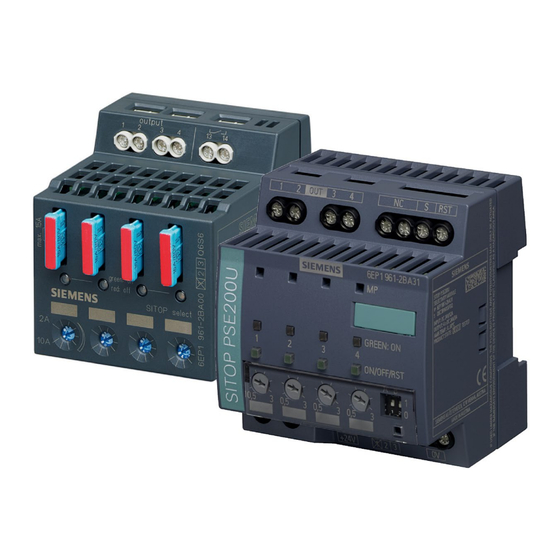
Selectivity modules
SITOP power supply
Selectivity modules
Manual
SITOP select
6EP1961-2BA00
SITOP PSE200U 3A
6EP1961-2BA11
SITOP PSE200U 10 A
6EP1961-2BA21
SITOP PSE200U 3 A
6EP1961-2BA31
SITOP PSE200U 10 A
6EP1961-2BA41
12.2014
C98130-A7579-A1-1-7629
___________________
Overview
___________________
Safety notes
Description, device design,
___________________
dimension drawing
___________________
Mounting/removal
Mounting position, mounting
___________________
clearances
___________________
Installation
___________________
Technical data
___________________
Safety, approvals, EMC
___________________
Environmental conditions
___________________
Environment
___________________
Service & Support
1
2
3
4
5
6
7
8
9
10
Advertisement
Table of Contents

Related Manuals for Siemens SITOP PSE200U 10 A


Summarization of Contents
Overview
Description
Explains the function of the selectivity module in distributing load current and monitoring individual branches.
Safety notes
Correct handling of the devices
Provides warnings about dangerous voltages and the need for qualified personnel and proper handling.
Description, device design, dimension drawing
Device description
Describes how the selectivity module distributes 24V DC output voltage across four load circuits and monitors current.
Connections and terminal designation
Details the terminal designations and connection types for different SITOP models.
Potentiometer
Explains the function of the potentiometer for setting the output current response threshold.
Status displays and signaling
Details the operating displays (LEDs) and signaling contacts for different SITOP models.
Buttons and selector switches
Describes the function of buttons and selector switches on the SITOP select and PSE200U modules.
Electronic overload shutdown and reset
Describes the electronic overload shutdown mechanism and characteristic for the SITOP select and PSE200U.
Setting the switch-on delay time
Explains how to set sequential switch-on delay times to manage inrush currents for SITOP select and PSE200U.
Block diagram
Presents the block diagrams for different SITOP selectivity module models.
Dimensions and weight
Provides dimension drawings and weight specifications for SITOP selectivity module models.
Mounting/removal
Installing the device in a housing or a control cabinet
Warns about installing the device in a housing or control cabinet accessible only to qualified personnel.
Mounting
Explains how to mount the device onto a standard mounting rail by pressing it down.
Removal
Describes the procedure for removing the device from a mounting rail using a screwdriver.
Use in hazardous zones
Provides warnings and requirements for using the device in hazardous zones.
Installation
Hazard due to electric shock
Warns about electric shock hazard before installation or maintenance, requiring power to be switched off.
Input side connection
Details the input side connection for the 24 V DC voltage supply to the selectivity module.
Output-side connection
Explains how to connect the load to the output terminals of the selectivity module.
Technical data
Input
Lists input voltage, range, and current ratings for different SITOP selectivity modules.
Output
Details output voltage, total tolerance, number of outputs, and adjustable response thresholds.
Shutdown characteristics
Presents shutdown characteristic curves for SITOP select and PSE200U under overload conditions.
Efficiency
Provides efficiency and power loss data for different SITOP selectivity modules.
Protection and monitoring
Details device protection (fuses) and operating display/signaling features.
Mechanical system
Lists connection systems, dimensions, weight, and mounting details for SITOP selectivity modules.
Environmental conditions
Ambient temperature
Specifies the operating ambient temperature range (0 to +60 °C) and testing conditions.
Transport and storage temperature
Defines the temperature range for transport and storage (-40 to +85 °C).
Humidity class
States the climatic class (3K3) for humidity according to EN 60721.
Mechanical stressing in operation
Details testing for vibration and shock resistance according to EN 60068 standards.
Atmospheric pressure
Specifies atmospheric pressure ranges for operation and storage, including altitude derating.
Environment
Disposal guidelines
Provides guidelines for recycling packaging and proper disposal of the product.
Service & Support
Technical support
Lists communication channels for technical support, including phone, e-mail, and online forms.
Technical documentation on the Internet
Directs users to the internet for operating instructions, manuals, and SITOP information.
SITOP Selection Tool
Introduces the SITOP Selection Tool for choosing the optimal power supply or DC-UPS.
Contact persons
Advises contacting the regional Siemens sales office for product usage questions.
Need help?
Do you have a question about the SITOP PSE200U 10 A and is the answer not in the manual?
Questions and answers