Table of Contents
Advertisement
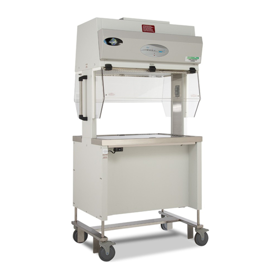
AllerGard™ ES Energy Saver Containment
Small Animal Transfer Station
Models
NU-620-300/400/500
NU-620-301/401/501
Operation & Maintenance Manual
June, 2019
Revision 5
Series 5
Manufactured By:
NuAire, Inc.
2100 Fernbrook Lane
Plymouth, MN 55447
Toll-Free: 1-800-328-3352
In Minnesota: (763)-553-1270
Fax: (763)-553-0459
OM0257
Page 1 of 38
Advertisement
Table of Contents

Related Manuals for NuAire AllerGard NU-620-400


Summary of Contents for NuAire AllerGard NU-620-400
- Page 1 AllerGard™ ES Energy Saver Containment Small Animal Transfer Station Models NU-620-300/400/500 NU-620-301/401/501 Operation & Maintenance Manual June, 2019 Revision 5 Series 5 Manufactured By: NuAire, Inc. 2100 Fernbrook Lane Plymouth, MN 55447 Toll-Free: 1-800-328-3352 In Minnesota: (763)-553-1270 Fax: (763)-553-0459 OM0257 Page 1 of 38...
- Page 2 A copy of the original factory test report is also appended to this manual. In case this manual and/or test report is lost or misplaced, NuAire retains a copy in our files. A replacement copy can be obtained by calling or writing NuAire, Inc.
- Page 3 AllerGard™ ES Energy Saver Containment Small Animal Transfer Station Models NU-620-300/400/500 NU-620-301/401/501 Operation & Maintenance Manual Table of Contents Section No. 1 ................General Description Section No. 2 ................Models & Features Section No. 3 ................Warranty Section No. 4 ................Shipments Section No.
-
Page 4: General Description
However, the NuAire Model NU-620 should not be used as a substitute for a Class II, Type A2 Biosafety Cabinet (BSC). The NU-620 is not a containment device for airborne particulate in low to moderate risk-hazard research as prescribed by the CDC/NIH Biosafety in Microbiological and Biomedical Laboratories. - Page 5 • are always accessible. • Should you encounter problems that are not detailed adequately in the operating instructions, please contact your NuAire Representative of NuAire technical Services. 1.2 Explanation of Symbols Safety alert symbol indicates a potentially hazardous WARNING situation which, if not avoided, could result in death of serious injury.
-
Page 6: Models & Features
Models & Features The Model NU-620 AllerGard™ ES Energy Saver Containment Small Animal Transfer Station is manufactured in 3 sizes: Dual Sided Single Sided 620-300 3 ft. (.91m) 620-301 3 ft. (.91m) 620-400 4 ft. (1.2m) 620-401 4 ft. (1.2m) 620-500 5 ft. - Page 7 OM0257 Page 7 of 38 June 2019...
- Page 8 OM0257 Page 8 of 38 June 2019...
- Page 9 OM0257 Page 9 of 38 June 2019...
-
Page 10: Warranty
Within the data packet sent with the unit. Shipments NuAire takes every reasonable precaution to assure that your ALLERGARD™ ES ENERGY SAVER CONTAINMENT SMALL ANIMAL TRANSFER STATION arrives without damage. Motor carriers are carefully selected and shipping cartons have been specially designed to insure your purchase. -
Page 11: Installation Instructions
Installation Instructions 5.1 Location The NU-620 Station can be located anywhere within the animal facility. However, for maximum product protection, the station should be used away from laboratory personnel traffic lanes, air vents (in or out), doors, and/or any other source of disruptive air currents. - Page 12 Biosafety Cabinets. After the initial certification, NuAire recommends that the station be recertified at a minimum on an annual basis and after every filter change or maintenance action or any time the operator feels it is necessary. Note that the station's filters and seals provide premium performance;...
- Page 13 AllerGard™ ES Energy Saver Containment Small Animal Transfer Station Models NU-620-300/400/500 NU-620-301/401/501 Catalog Number NU-620-300 NU-620-400 NU-620-500 Catalog Number NU-620-301 NU-620-401 NU-620-501 Nominal 3 foot (0.9m) Nominal 4 foot (1.2m) Nominal 5 foot (1.5m) Performance Specifications NU-620-XX0 Product / Personnel ISO 4 / Improved Allergen ISO 4 / Improved Allergen ISO 4 / Improved Allergen...
- Page 14 Operating the NU-620 6.1 Aeromax™ Control System 6.1.1 Overview The Aeromax™ control system is designed to service the control requirements of the NU-620. The Aeromax™ control system consists of an electronic module that will perform the following functions: • Easy user interface via LED’s and function keys •...
- Page 15 OM0257 Page 15 of 38 June 2019...
- Page 16 6.1.2 Front Panel The control system front panel contains the following functions described in detail (see Drawing BCD-16521). 6.1.2.1 Blower Keys The blower key controls the ON/OFF power to the blower. LED above key indicates: full green for blower on, blinking green for blower pending and full red for blower alarm.
- Page 17 6.1.3 Aeromax™ Control System Power After the NU-620 is plugged into the appropriate facility line power the control system will power up. The control panel will also indicate the power up status by blinking the red alarm LED. Pressing any key will acknowledge the power up status and turn off the blinking red alarm LED.
- Page 18 6.1.8 Operator Accessible Functions 6.1.8.1 Access and Navigation To access the operator accessible functions, Press and hold the key, then enter the 3-key sequence for the desired function, then release the • key and follow each instruction set. Note: Pressing the key at any time will abort and exit the process without saving any changes made.
- Page 19 6.1.8.3 Blower Password The blower on/off password allows the cabinet user to place a 3 key sequence requirement to turn the blower on or off. The 3-key sequence for the blower password will be a combination of the hidden and blower keys. •...
- Page 20 Operating Guidelines It is acceptable and sometimes recommended to operate the station continuously. The station will then remain in its initially clean condition. If for any reason the unit is turned off for some time, daily or weekly, turn the station on and run for 10 minutes before using.
- Page 21 Further information is available at the following: http://www.parrinst.com/wp- content/uploads/downloads/2011/07/Parr_Stainless-Steels-Corrosion-Info.pdf NOTE: NuAire does not offer any product warranty with respect to cleaning material compatibility. USE AT YOUR OWN RISK! The information provided above is from raw material suppliers and known general source documents for use to develop application cleaning SOP’s.
-
Page 22: General Maintenance
The casters should be inspected annually for tightness. If they are found to be loose they should be removed, inspected, and re-installed with BLUE Loctite. If they are bent or loose replacement may be necessary, please contact NuAire’s Technical Support 1-800-328-3352. 8.1.5 Push\Pull Bars The push\pull bars should be inspected annually and tightened as necessary. - Page 23 10) Tighten filter frame hold down spring clamps evenly, so filter gasket will have equal pressure from all areas. 11) Replace protective screen, side access cover, and filter access cover once filter is installed. USE ONLY NUAIRE SPECIFIED FILTERS FOR REPLACEMENT Description:...
- Page 24 NOTE: THIS WORK SHOULD BE DONE ONLY BY A QUALIFIED TECHNICIAN WHO CAN MEASURE VOLTAGE AND AIRFLOW FROM THE FILTERS WITH A SUITABLE VELOMETER. NuAire provides the following adjustment to calibrate the airflow within the station. This is: Blower speed adjustment via motor voltage regulators...
- Page 25 The station is considered to be certifiable if the following airflow and voltage measurements are present: Downflow Average: 60 LFPM + 5 LFPM (.3 m/s + .025 m/s) Single Side Model Exhaust Airflow 550 + 50 CFM (935 + 85 CMH) 620-301 625 + 50 CFM (1060 + 85 CMH) 620-401...
-
Page 26: Alternate Method
Right end red LED indicates active blower speed adjust The red LED will blink as soon as any adjustments are made and will continue to blink as the motor rpm settles. Once the red LED stops blinking, the motor will run steady state at the new percentage. - Page 27 8.7 Filter Integrity Check In order to check filter, the HEPA filter media must be directly accessible. Remove supply diffuser and exhaust protective screen to access the filters. P.A.O. upstream concentration ports are available on both the top and bottom filter housings if needed.
- Page 28 PresurFlow™ Alarm Set Points The PresurFlow™ alarm setpoints are preset based on the calibration setpoint. Once the calibration setpoint is entered, based on a nominal airflow velocity, the associated pressure sensor value is entered as the nominal pressure value. The high and low alarm setpoints are preset with an associated pressure offset value within the acceptable cabinet airflow range.
- Page 29 8.9 Decontamination No maintenance should be performed on the interior of the Allergard cabinet (area behind access panels) unless the cabinet has been microbiologically decontaminated, is known to be biologically clean, or know to be chemically inert. If microbiological decontamination is necessary, use the following procedure: 1.
- Page 30 Polycarbonate Material Compatibility OM0257 Page 30 of 38 June 2019...
- Page 31 Isolate output of circuit by disconnecting control center connectors, light circuit, AC or DC motor voltage, etc. to isolate the short. Hydraulic Lift Lift system does not function Call NuAire Service to resolve. properly (1-800-328-3352) PresurFlow™ left red LED indicator on and PresurFlow™ reading low flow Check airflow values.
- Page 32 10.2 Option Parameters The option parameter menu allows A QUALIFIED TECHNICIAN to configure several different optional parameters per the menu as described below. 10.2.1 Sync Function with Active Blower To access the option parameter menu, perform the following: • Press and hold key, then press hidden - Blower - Fluorescent keys sequentially.
- Page 33 Require Password – Normally it is not required to use a password (i.e. 3 key press sequence of the blower and hidden key). If the option is turned on, it would be required to use the correct password to turn on the blower. The default password once turned on is blower- hidden-blower keys in sequence.
-
Page 34: Remote Contacts
11.0 Remote Contacts The NU-620 has several contact closures for remote sensing of various functions. 11.1 Fan Relay The fan relay contacts are normally open and closed contact closure outputs that are activated whenever the blower key is pressed and the blower key LED indicator is on or blinking. Contact ratings are 250 VAC maximum at 2 Amps. 11.2 Alarm Relay The alarm relay contacts are normally open and closed contact closure outputs which are activated whenever an airflow alarm condition occurs. -
Page 35: Electrical/Environmental Requirements
12.0 Electrical/Environmental Requirements 12.1 Electrical: (Supply voltage fluctuations not to exceed +/-10%) NU-620-300/301 60 Hz 1 Phase 12 Amps NU-620-400/401 60 Hz 1 Phase 12 Amps NU-620-500/501 60 Hz 1 Phase 12 Amps 12.2 Operational Performance - Indoor Use Only Environment Temperature Range: 60°F - 90°F (15.6°C - 32.2°C) Environment Humidity:... - Page 36 13.0 Disposal and Recycle Cabinets that are no longer in use and are ready for disposal contain reusable materials. ALL components with the exception of the HEPA filters may be disposed and/or recycled after they are known to be properly disinfected. ...
- Page 37 14.0 PM Checklist Prefilters – Check Daily Check supply prefilter Check exhaust mesh prefilter Check exhaust prefilter * Clean (black washable foam) or replace (white disposable) if necessary Worksurface – Yearly\As Needed Clean the work surface top Clean under the work surface Check for rubber feet on worksurface and prop rods * Replace if missing Check tightness of acorn nuts on prop rod supports...
- Page 38 OM0257 Page 38 of 38 June 2019...
Need help?
Do you have a question about the AllerGard NU-620-400 and is the answer not in the manual?
Questions and answers