Table of Contents
Advertisement
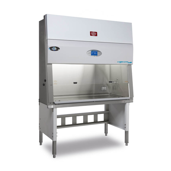
LabGard® ES Energy Saver
Class II, Type A2 Laminar Flow
Biosafety Cabinet
Models
NU-545-300/400/500/600
Bench/Console
Operation and Maintenance Manual
September, 2017
Revision 3
Series 1
Manufactured By:
NuAire, Inc.
2100 Fernbrook Lane
Plymouth, MN 55447
Toll-Free: 1-800-328-3352
In Minnesota: (763)-553-1270
Fax: (763)-553-0459
OM0216
Page 1 of 100
Advertisement
Table of Contents

Related Manuals for NuAire LabGard ES NU-545-400


Summary of Contents for NuAire LabGard ES NU-545-400
- Page 1 Class II, Type A2 Laminar Flow Biosafety Cabinet Models NU-545-300/400/500/600 Bench/Console Operation and Maintenance Manual September, 2017 Revision 3 Series 1 Manufactured By: NuAire, Inc. 2100 Fernbrook Lane Plymouth, MN 55447 Toll-Free: 1-800-328-3352 In Minnesota: (763)-553-1270 Fax: (763)-553-0459 OM0216 Page 1 of 100...
- Page 2 NSF/ANSI 49. Please read this manual carefully to familiarize yourself with proper installation, maintenance and operation of the cabinet. Other reference and guideline materials are available through the following web sites; www.hc-sc.gc.ca www.cdc.gov/od/ohs/ www.absa.org www.cabs-acsb.ca www.ebsaweb.eu www.inspection.gc.ca www.who.int www.biosafety.be www.hse.gov.uk www.nsf.org www.cetainternational.org www.nuaire.com OM0216 Page 2 of 100 September/2017...
- Page 3 A copy of the original factory test report is also appended to this manual. In case this manual and/or test report is lost or misplaced, NuAire retains a copy in our files. A replacement copy can be obtained by calling or writing NuAire, Inc.
-
Page 4: Table Of Contents
LabGard® ES Energy Saver Class II, Type A2 Laminar Flow Biosafety Cabinet Models NU-545-300/400/500/600 Operation and Maintenance Manual Table of Contents Section No. 1 ............. General Information Section No. 2 ............. Models and Features Section No. 3 ............. Warranty Section No. 4 ............. Shipments Section No. - Page 5 Biosafety Cabinet Models NU-545-300/400/500/600 Manufactured by: NuAire, Inc. - Plymouth, Minnesota, U.S.A. General Information 1.1 Description The LabGard® ES Model NU-545 Laminar Flow Biosafety Cabinet (LFBSC) is a bench/table top model, optionally available with a base support stand, for operation as a console model. The LabGard® ES model NU-545 utilizes an Energy Saver DC ECM motor optimally determined forward curved fan for each model size/width to maximize both energy efficiency and filter loading capacity.
- Page 6 Should you encounter problems that are not detailed adequately in the operating instructions, please contact your NuAire Representative of NuAire technical Services. 1.3 Explanation of Symbols Safety alert symbol indicates a potentially hazardous situation which, if not avoided, could result in death of WARNING serious injury.
- Page 7 OM0216 Page 7 of 100 September/2017...
- Page 8 Models and Features The model NU-545, LabGard® ES, Class II, Type A2 Laminar Flow Biosafety Cabinet is manufactured in four sizes: 3 ft. (.9m) 4 ft. (1.2m) 5 ft. (1.5m) and 6 ft. (1.8m) OM0216 Page 8 of 100 September/2017...
- Page 9 OM0216 Page 9 of 100 September/2017...
- Page 10 OM0216 Page 10 of 100 September/2017...
- Page 11 OM0216 Page 11 of 100 September/2017...
- Page 12 OM0216 Page 12 of 100 September/2017...
- Page 13 OM0216 Page 13 of 100 September/2017...
- Page 14 Claims under this warranty should be directed to NuAire, Inc. setting forth in detail the nature of the defect, the date of the initial installation and the serial and model number of the equipment.
-
Page 15: Location
CDC/NIH and NSF, it is strongly recommended that the cabinet be exhausted to the outside. NuAire offers a canopy type of exhaust transition, which will capture the exhaust efflux from the cabinet. -
Page 16: Set-Up Instructions
5.2.4 Gas Service NuAire doesn't recommend the use of natural gas within the LFBSC, but if gas service is determined to be necessary for the application, appropriate safety measures must take place. All NuAire LFBSC's have precautionary warning labels that say the following:... - Page 17 5.2.5 Plumbing Services Service ball valves with the type of service specified by the removable button on the handle are located in the work zone. The service ball valves are not recommended for pressure over 75 p.s.i. (5.2 BAR). Reducing valves should be installed external to the cabinet if necessary.
-
Page 18: Testing Methods And Equipment
5.3 Testing Methods and Equipment After installation and prior to use, NuAire recommends that the cabinet be tested or commissioned to factory standards. As part of testing, the certifier should go through the following initial checklist to assure all aspects of the LFBSC installation are complete and ready for testing. - Page 19 LabGard® ES Energy Saver Class II Type, A2 Laminar Flow Biosafety Cabinet Models NU-545-300/400/500/600 Catalog Number Catalog Number NU-545-300 NU-545-400 NU-545-500 NU-545-600 Nominal 3 foot (0.9m) Nominal 4 foot (1.2m) Nominal 5 foot (1.5m) Nominal 6 foot (1.8m) Performance Specifications NSF/ANSI 49 NSF/ANSI 49 NSF/ANSI 49...
-
Page 20: Touchlink™ Control System
Operating the NU-545 6.1 TouchLink™ Control System 6.1.1 Overview The Biosafety Cabinet Control (BSCC) system is designed to service the control requirements of the NU-545 Biosafety Cabinet. The control system is a self-contained microprocessor driven module that will perform the following functions: ... - Page 21 Standby Mode When the BSC is not in use, the TOUCHLINK LCD screen will display a large NuAire logo, the icons along the top and the time and date at the bottom right as shown below. Any of the function icons, except the blower, that initiates Run Mode, may be turned on and off in standby mode.
- Page 22 If present standby/run mode alarms will be both visual and audible, the Red LED oval under the LCD display will turn on, and the TOUCHLINK LCD screen will also display a description of the alarm in place of the NuAire Logo.
- Page 23 6.1.6 Timer Icons The timer icon, when pressed will provide a list of time functions available for use. Below is a description of each timer function. MENU LABORATORY TIMER PURGE TIMER DOWN OUTLET TIMER UV LIGHT TIMER ENTER AUTO RUN TIMER xx:xx xx/xx/xx Timer Functions...
- Page 24 Outlet Timer - This timer controls how long the outlet remains on after the outlet icon has been pressed to turn on the outlet. If timer is zero, the outlet will stay on until turned off. MENU OUTLET TIMER CURRENT SETTING = 0.00 MINS.
- Page 25 Once into the selected day, press UP or DOWN to enter the on/off times. Use the >> and << to select hours or minutes. Press SWITCH to toggle between auto time on and auto time off. Press SAVE after each time entry. Press DIS to disable auto timer for the day being reviewed.
- Page 26 Menu Items Calibration/Service - A password protected area used by certification or service personnel to set up and calibrate the cabinet for certification or commissioning. Time/Date - This menu item provides the ability to set the time and date displayed on the LCD screen. Time displayed is real time and will not automatically adjust for day light saving time.
- Page 27 Password - This menu item provides the ability to change the user password from the default value of 1234. MENU SET PASSWORD DOWN DEFAULT PASSWORD ENTER xx:xx xx/xx/xx Set Password EXIT MENU BACK ENTER OLD PASSWORD XXXX ENTER xx:xx xx/xx/xx ...
- Page 28 Set Password MENU EXIT BACK ENTER NEW PASSWORD XXXX SAVE xx:xx xx/xx/xx Decon Cycle - This menu item provides the ability to perform an automated or manual decon procedure. (See decontamination section for instructions). Screen Set-Up - This menu item provides the ability to alter LCD screen display background contrast and audible touch screen tone.
- Page 29 MENU SETTING MAIN SCREEN BACKGROUND COLOR SELECT COLOR BELOW TO CHANGE WHITE GREEN BLUE GRAY xx:xx xx/xx/xx MENU SETTING SCREEN BORDER COLOR SELECT COLOR BELOW TO CHANGE WHITE GREEN BLUE GRAY xx:xx xx/xx/xx MENU TOUCH DISPLAY TONE IS ON PRESS ON AND OFF TO CHANGE SETTING WHEN TOUCHSCREEN TONE IS ON, AN AUDIBLE TONE WILL SOUND TO INDICATE A SAVE...
- Page 30 MENU SCREEN SAVER OPTION SETTING 60 THIS OPEION DETERMINES HOW LONG THE DISPLAY WILL REMAIN ACTIVE AFTER THE BLOWER IS TURNED OFF. VALID RANGE IS 0 - 240 MINUTES. SETTING THE VALUE TO 0 TURNS THE SCREEN SAVE SAVER OFF. PRESS UP/DOWN TO CHANGE THE VALUE.
-
Page 31: Operating Guidelines
6.2 Operating Guidelines The intent herein is to present general operational guidelines that will aid in the use of the Laminar Flow Biosafety Cabinet (LFBSC) to control airborne contaminants of low to moderate risk as stated in Technical Report Number FPS 56500000001, prepared by Dow Chemical U.S.A. - Page 32 6.2.4 Utilize Unidirectional Air Flow The operator must keep two important facts in mind: (1) The air, as supplied to the work area through filters from the top, is contaminant free and (2) Airborne contamination generated in the work area is controlled by the unidirectional flow of parallel air streams in a top-to-bottom direction.
-
Page 33: Operating Sequence
6.3 Operating Sequence 6.3.1 Start Up Turn on cabinet blower and lights, check air intake and exhaust portals of the cabinet to make sure they are unobstructed. The electronic airflow control system will automatically control airflows to specified setpoints. However, upon filter loading, the cabinet may be required to be re-balanced or filters replaced. Only a qualified maintenance technician should perform cabinet balancing and filter replacement. - Page 34 6.3.5 Perform Work The work can now be performed. The technician performing the work is encouraged to wear a long-sleeved gown with knit cuffs and rubber gloves. This will minimize the shedding of skin flora into the work area and concurrently protect the hands and arms from viable agent contamination.
-
Page 35: Ergonomics
6.4 Ergonomics Ergonomics, the study or accommodation of work practices is extremely important for proper cabinet usage and user health and safety. An evaluation of normal work practices should be performed with each user when working in a cabinet. Evaluation criteria should be at a minimum: Proper user posture b. - Page 36 6.6.2 Procedure Make sure that the cabinet remains in operational mode with internal blower on. b. Open the hinged or sliding view screen and secure in the full open position. With the view screen in the full open position, personnel protection CAUTION is compromised and a full faced HEPA filtered respirator must be worn.
-
Page 37: Decontamination
General Maintenance All maintenance actions on this equipment must be performed by a qualified technician who is familiar with the proper maintenance procedures required CAUTION for this equipment. This includes both certification as well as repair. 7.1 Decontamination No maintenance should be performed on the interior of the LABGARD ES cabinet (area behind access panels) unless the cabinet has been microbiologically decontaminated, is known to biologically clean, or known to be chemically inert. - Page 38 Select MANUAL DECON or AUTO DECON-H2O2/CD. The manual decon process requires the use of NuAire accessory, Front and Top Seal Plates, (i.e. NU-985-301,401,501,601). The Auto Decon - H2O2/CD requires the use of NuAire accessory Auto Decon Exhaust Seal Plate (i.e. NU-985-302,402,502,602). Please contact NuAire Technical Service for further assistance.
- Page 39 7.1.1 Manual Decon 1. Disconnect power to the cabinet. Remove screws at each upper side of the control center and allow the control center to rotate down, resting on the safety straps. Disconnect electrical connectors on left side. Disconnect electrical from right side. (Be sure to note the location of the supply and exhaust sensor wires before disconnecting them from the main board).
- Page 40 Slow and deliberate motions are necessary when working in the interior of the cabinet, in order to minimize the generation of particulates. Please consult with NuAire, Inc. about any unique contamination problems. Normally, no preventive maintenance is required on the interior of the cabinet (i.e., the area behind the access panel containing the HEPA filters and motor (blower assembly).
- Page 41 7.1.2 Auto Decon - H2O2/CD The Auto Decon - H2O2/CD process is intended to be used with any automated cabinet decontamination process (i.e. hydrogen peroxide, chlorine dioxide, paraformaldehyde, etc.). The automated decon process parameters are typically set up independently of the cabinet. Inlet and outlet ports from the automated decon machine are connected to the cabinet.
- Page 42 OM0216 Page 42 of 100 September/2017...
- Page 43 Enter DECON FULL CYCLE TIME ranging from 30 to 720 minutes. This time should be the same as the automated decon machine used for the process. MENU DECON FULL CYCLE TIME 120 MINUTES DOWN USE UP/DOWN TO CHANGE SETTING SAVE PRESS SAVE TO START THE NEW VALUE PRESS SAVE TO EXIT xx:xx...
- Page 44 Decon blower duty cycle allows the cabinet blower to run at a lower speed when used during the decontamination process. The default setting has been determined as a minimum value, but adjustments can be made if necessary. MENU SET DECON BLOWER DUTY XXX DUTY STEPS DOWN USE UP/DOWN TO CHANGE SETTING...
-
Page 45: Led Lamp Bulb Replacement
Once the password has been entered, the procedure screen will appear. MENU 1) REMOVE ARMREST 2) INSTALL PLATE OR COVER OVER EXHAUST FILTER AREA 3) CONNECT DECON GAS INLET TO CABINET INLET GAS START FITTING ON TOP LEFT OF CABINET 4) CONNECT DECON GAS RETURN TO CABINET RETURN GAS FITTING ON EXHAUST PLATE 5) LOWER WINDOW TO FULL DOWN POSITION... - Page 46 7.3.1 Procedure Disconnect electrical power from the cabinet before attempting any CAUTION maintenance action. Step 1: Remove screws at each upper side of the control center and allow the control center to rotate down, resting on the safety straps. Second, remove the front decorative panel which is held into position by (3) knurled nuts on the top edge and snap fit bullet catches on the bottom.
- Page 47 Step 4: Filter Installation When installing new filters, USE ONLY NUAIRE SPECFIED FILTERS FOR REPLACEMENT. Description: Supply HEPA Filter Exhaust HEPA Filter Efficiency: 99.99% @ 0.3 Micron 99.99% @ 0.3 Micron 100 fpm @ .55 .05" w.g. per sq. ft.
-
Page 48: Sliding Window Replacement And Manual Adjustment
7.4 Sliding Window Replacement & Manual Adjustment The sliding window replacement is accomplished by removing the front decorative panel, control center, and window glide assemblies. The sliding window adjustment may be required due to everyday use over the life of the cabinet. Both the right and left window glides are adjustable by a set screw and tension screw method. - Page 49 7.5.2 Calibration/Service Menu The Calibration/Service menu provides a list of sub-menu items to accomplish all service tasks. For airflow calibration, only the first three sub-menu items are used in the calibration process. MENU SETPOINTS/LIMITS DOWN SENSOR SETUP NIGHT SETBACK SERVICE ENTER OPTION SETUP DIAGNOSTICS...
- Page 50 7.5.2.2 Setpoints/Limits The airflow setpoints and alarm limits may also be verified or altered. Typically these default values are factory set based on the cabinet type, model and size as previously discussed. However, they may be altered in special cases for modified cabinets. The setpoint establishes the airflow values that are to be maintained. The high low limits establish the alarm boundaries from the nominal setpoint.
- Page 51 The blower speed control system adjusts the cabinet's total volume of airflow while the choke adjusts or balances the exhaust airflow as well as makes up for filter resistance tolerances. Since it has been NuAire's experience that the filters may not "load" evenly, both adjustments are necessary for proper cabinet performance.
- Page 52 7.5.3.1 Downflow Calibration Access Calibration/Service menu. Step 1: Press SENSOR SETUP menu item to access sensor calibration menu. CALIBRATE DOWNFLOW SENSOR CALIBRATE EXHAUST SENSOR DOWN FIND NEW DOWNFLOW SENSOR ENTER FIND NEW EXHAUST SENSOR ALARM VERIFICATION Step 2: Press CALIBRATE DOWNFLOW SENSOR to access individual calibration screen.
- Page 53 Step 4: Press BLOWER DUTY CYCLE to adjust blower speed. The objective of this spot check is to obtain the desired downflow average velocity as close as possible to the stated goal of 60 LFPM (.30 m/s) MENU MOTOR RPM = XXXX DOWN BLOWER DUTY CYCLE = XX.XXX SAVE...
- Page 54 7.5.3.2 Inflow Calibration NOTE: INFLOW CALIBRATION MUST BE MADE IMMEDIATELY FOLLOWING DOWNFLOW CALIBRATION. THIS ASSURES THE CORRECT BALANCE OF DOWNFLOW TO INFLOW AS RELATED TO THE AIRFLOW MONITOR SENSOR CALIBRATIONS. Step 1: Access sensor setup menu. CALIBRATE DOWNFLOW SENSOR DOWN CALIBRATE EXHAUST SENSOR FIND NEW DOWNFLOW SENSOR...
- Page 55 NOTE: The choke plate adjustment requires standard blade screwdriver. To adjust, loosen the liquid- tight fitting around the choke adjustment shaft. While monitoring the exhaust flow to check position, turning the choke adjustment shaft clockwise will open the choke while turning counter clockwise closes the choke.
- Page 56 7.5.3.3 Alarm Verification If desired, the alarm setpoint can be verified by entering into the alarm verification menu. CALIBRATE DOWNFLOW SENSOR DOWN CALIBRATE INFLOW SENSOR FIND NEW DOWNFLOW SENSOR ENTER FIND NEW INFLOW SENSOR ALARM VERIFICATION MOTOR RPM = 1086 DOWN BLOWER DUTY CYCLE = 41.245 ENTER...
- Page 57 Table 7.0 Recommended Measurement Methods for Cabinet Downflow and Inflow A. Downflow Measurement Recommended Instruments: TSI 8355 Thermo anemometer b. Procedure: Supply filter efflux is measured on a grid, in a horizontal plane 4 inches (102mm) above the bottom edge of the window.
- Page 58 Alternate Procedure: The alternative procedure to determine inflow velocity uses a thermo anemometer in a constricted window access opening of 3 inches (76mm) with the armrest removed. Inflow air velocity is measured in the center of the constricted opening 1-1/2 inches (38mm) above the work access opening on the following specified grid. Use the correction factor table to calculate the inflow velocity.
-
Page 59: Hepa Filter Leak Test
7.6 HEPA Filter Leak Test In order to check filter and filter seal integrity, the HEPA filter media and seals must be directly accessible, by the measuring instrument. The challenge material (i.e. PAO) should be supplied in the rear center of the workzone over the intake slots. The upstream challenge port being common for both filters in located on top of the cabinet. -
Page 60: Airflow Smoke Pattern Test
Entry into the Calibration/Service functions requires a service password for entry. After pressing Calibration/Service menu item, a password screen will appear. The default password is “9876”. Once the service password is entered the Calibration/Service menu will appear. MENU EXIT ENTER PASSWORD BACK XXXX ENTER... -
Page 61: Site Installation Assessment Test
7.8 Site Installation Assessment Tests These tests are performed to verify the sash position, airflow or pressure setpoint where an audible and/or visual alarm will activate to signify unfavorable operating conditions within the Biosafety cabinet and/or the remote exhaust blower, and canopy connection performance. -
Page 62: Main Control Board Description And Replacement
7.10 Main Control Board Description & Replacement To access the main control board for fuse or board replacement, remove screws at each upper side of the control center and allow the control center to rotate down, resting on the safety straps. Now the main control board is exposed for service. - Page 63 7.10.4 Cabinet Reset The main control board has two software operating resets available for qualified service personnel. The two types are the following: Factory Reset - Resets setpoints and selected option settings. Factory reset should be used in the event the system memory develops an error in operation.
- Page 64 Also during this 1 minute, an audible signal of the reset process will occur. Once the reset process is complete the display screen will revert back to the NuAire logo main menu. At this point the cabinet MUST be turned off to complete the process.
-
Page 65: Digital Airflow Sensor Description And Replacement
Step 1: NOTE ALL ERROR MESSAGES. Error message will appear in place if the NuAire logo with “Active Alarms” and the alarm type below. Step 2: VERIFY ERROR MESSAGES. Error messages can be verified by cleaning the error function by either turning the blower or the cabinet on and off. - Page 66 Error Message Troubleshooting Guide Error Message Indicator Correction Window Alarm Sliding window is above its standard working Verify standard working height and window micro switch (Window High) height or micro switch is not operating properly. operation. Window Alarm Sliding window is below its standard working Verify standard working height and window micro switch (Window Low) height or micro switch is not operating properly.
- Page 67 8.2 Calibration/Service Menu 8.2.1 General As with the airflow calibration process, the service menu should only be accessed by a Service Technician that is familiar with the product. MENU CALIBRATION/SERVICE TIME/DATE DOWN PASSWORD CABINET DECONTAMINATION ENTER SCREEN SETUP FILTER STATUS xx:xx xx/xx/xx Entry into the Calibration/Service functions requires a service password for entry.
- Page 68 8.2.2.1 Cabinet Type/Motor Type The cabinet type can be verified or changed in the control system. The cabinet type default information controls unit of measure, setpoints and limits based on the type and size of cabinet. To verify, press CABINET TYPE. The current type of cabinet will be designated. Again to verify, press the correct Cabinet Type and the Model/Size of the current selected cabinet model will be designated.
- Page 69 8.2.2.2 Setpoints/Limits The airflow setpoints and alarm limits may also be verified or altered. Typically these default values are factory set based on the cabinet type, model and size as previously discussed. However, they may be altered in special cases for modified cabinets. The setpoint establishes the airflow values that are to be maintained. The high low limits establish the alarm boundaries from the nominal setpoint.
- Page 70 8.2.2.3 Digital Sensor Setup The sensor setup menu is used for both calibration and sensor replacement if necessary. For sensor calibration process, see airflow calibration section. For sensor replacement, use the “Find new downflow / exhaust” menu’s below. This would also be required after performing a MASTER RESET. If finding or replacing one or both sensors, the downflow sensor will always have to be connected and found first.
- Page 71 8.2.2.4 Night Setback The optional night setback is used to allow the cabinet to run at a reduced airflow rate to keep the workzone sterile and maintain containment in a static environment. The night setback is calibrated as a percentage of the nominal setpoint and should be adjusted during the certification process to the desired level.
- Page 72 Run Times This parameter allows the service technician to view, alter, or reset both UV light and motor blower run timer. Select desired run time parameter from menu. MENU UV RUN TIME DOWN BLOWER MOTOR RUN TIME ENTER PRESS MENU TO EXIT xx:xx xx/xx/xx ...
- Page 73 Main Component Replacement This parameter allows the service technician to view and update HEPA filters, blower motor, main control board and sensor installation dates. MENU SUPPLY HEPA FILTER MM / DD / YYYY EXHAUST HEPA FILTER MM / DD / YYYY BLOWER MOTOR MM / DD / YYYY DOWN...
- Page 74 Certification Date This parameter allows the service technician to view and update the current certification date. MENU LAST CERTIFICATION DATE MM / DD / YYYY PRESSING SET ENTER A CERTIFICATION DATE PRESS DUE TO SET WHEN NEXT CERTIFICATION WILL BE REQUIRED. PRESS MENU TO EXIT xx:xx xx/xx/xx MENU...
- Page 75 Power Window This parameter allows for the power window option to operate. When the power window option is factory installed this parameter will allow the user display menu to indicate the power window up and down icons. The power window option functions using a 24 Vdc motor and internal feedback encoder to determine window position.
- Page 76 Power Window Test Power window test allows the movement of the power window for all positions including the lowest position, with the armrest removed, used for the decon process. MENU AUTO WINDOW TEST PRESS THE WINDOW KEYS TO MOVE THE WINDOW THROUGH ITS WORKING RANGE.
- Page 77 8.2.2.6 Option Set Up The option set up menu allows A QUALIFIED TECHNICIAN to configure several different optional parameters per the menu below. Each parameter sub-menu will be described as well as the display will the default conditions as shown. MENU AIRFLOW DISPLAY AVERAGING UV WINDOW INTERLOCK...
- Page 78 UV Window Interlock This parameter allows for the selection of the window closed switch to be interlocked with the UV light option. When the window interlock is on, the window must be closed for the UV light to operate. When the window interlock is off the UV light can be turned on regardless of the window position.
- Page 79 Alarm Silence This parameter allows for the selection of the alarm silence key function. When the alarm silence function is on, all current and future alarms will be silenced for the designated alarm silence time (i.e. default time is 15 minutes). When the alarm silence function is off, all current alarms will be silenced for the designated alarm silence time.
- Page 80 Motor Blower Lockout This parameter allows the access to turn the blower on or off to be restricted by the use of a password. When the blower lockout is on, pressing the blower icon will produce a numerical password screen. The default password is “1234”...
- Page 81 AUX Relay Function This parameter allows for the selection of the AUX relay function. When the AUX relay is on, the AUX relay function will be identical to the fan relay. When the AUX relay function is off, the AUX relay function provides delay On/Off option.
- Page 82 Blower LED Light Interlock This parameter allows for the selection of the LED light option to be interlocked to the blower. When the blower FL light interlock is on, the LED light operation will be interlocked to the blower. When the blower FL light interlock is off, the LED light can be turned on at any time.
- Page 83 Accessory Outlet This parameter allows for the selection of the power connection that supplies power to the exhaust decon chamber to be interlocked to the blower. This parameter would only be used in special cases and does not affect operation during an auto decon cycle. MENU ACCESSORY OUTLET OPTION IS OFF...
- Page 84 Alarm Silence Time This parameter allows for the selection of time to determine how long the audible alarm shall be silenced. The time is displayed in minutes with a programmable range of 1 to 60. MENU ALARM SILENCE TIME OPTION SETTING = 15 THIS OPTION DETERMINES HOW MANY MINUTES THE AUDIBLE ALARM WILL BE SILENCED WHEN SILENCE IS PRESSED.
- Page 85 8.2.2.7 Diagnostics The diagnostics menu allows A QUALIFIED TECHNICIAN to exercise the control system’s inputs and outputs. Each of these has its own menu screen to excise the control system. Select menu screen as desired. MENU DOWN TEST OUTPUTS READ INPUTS ENTER xx:xx xx/xx/xx...
- Page 86 When the downflow sensor is uncovered, the motor/blower voltage should decrease and airflow readings should be within the calibration range. If the motor/blower voltage does not change, an airflow sensor problem could exist. Please consult with NuAire Technical Service.
- Page 87 Remote Contacts The NU-545 has several contact closures for remote sensing of various functions. 9.1 Fan Relay The fan relay contacts are dual normally open contact closure outputs which are activated whenever the blower is turned on. Contact ratings are 250 VAC maximum at 2 Amps. 9.2 Alarm Relay The alarm relay contacts are dual normally open contact closure outputs which are activated whenever an airflow alarm condition occurs.
-
Page 88: Ultraviolet Light
10.0 Optional Equipment 10.1 Ultraviolet Light Ultraviolet light will injure your eyes. Avoid direct viewing at all times. CAUTION Personnel should not be present when ultraviolet lamp is on 10.1.1 Overview The germicidal ultraviolet is primarily intended for the destruction of bacteria and other microorganisms in the air or on directly exposed surfaces. - Page 89 Energies Required to Destroy Some Microorganisms by Ultraviolet Radiation’s (e) Microwatt Microwatt Mold Spores seconds Protozoa seconds per cm/2 per cm/2 Penicillium roqueforti 26,400 Paramecium 200,000(a) Penicillium expansum 22,000 Penicillium digitiatum 88,000 Nematode Eggs 40,000(b) Aspergillus glaucus 88,000 Aspergillus flavus 99,000 Algae 22,000(c)
- Page 90 11.0 Electrical/Environmental Requirements 11.1 Electrical (Supply Voltage Fluctuations Not to Exceed +/- 10%) *NU-545-300 115 VAC, 60 Hz, 1 Phase, 10 Amps *NU-545-400 115 VAC, 60 Hz, 1 Phase, 14 Amps *NU-545-500 115 VAC, 60 Hz, 1 Phase, 16 Amps *NU-545-600 115 VAC, 60 Hz,...
- Page 91 12.0 Disposal and Recycle Cabinets that are no longer in use and are ready for disposal contain reusable materials. ALL components with the exception of the HEPA filters may be disposed and/or recycled after they are known to be properly disinfected. ...
- Page 92 OM0216 Page 92 of 100 September/2017...
- Page 93 OM0216 Page 93 of 100 September/2017...
- Page 94 OM0216 Page 94 of 100 September/2017...
- Page 95 OM0216 Page 95 of 100 September/2017...
- Page 96 OM0216 Page 96 of 100 September/2017...
- Page 97 OM0216 Page 97 of 100 September/2017...
- Page 98 OM0216 Page 98 of 100 September/2017...
- Page 99 OM0216 Page 99 of 100 September/2017...
- Page 100 OM0216 Page 100 of 100 September/2017...
Need help?
Do you have a question about the LabGard ES NU-545-400 and is the answer not in the manual?
Questions and answers