Table of Contents
Advertisement
Quick Links
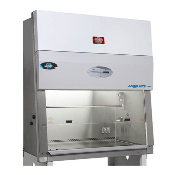
LabGard® ES Energy Saver
Class II, Type A2 Laminar Flow
Biosafety Cabinet
Models
NU-543-300J/400J/500J/600J
Bench/Console
Operation and Maintenance Manual
April, 2021
Revision 6
Series 1
Manufactured By:
NuAire, Inc.
2100 Fernbrook Lane
Plymouth, MN 55447
Toll-Free: 1-800-328-3352
In Minnesota: (763)-553-1270
Fax: (763)-553-0459
OM0266
Page 1 of 71
Advertisement
Table of Contents

Related Manuals for NuAire LabGard NU-543-300J


Summary of Contents for NuAire LabGard NU-543-300J
- Page 1 Class II, Type A2 Laminar Flow Biosafety Cabinet Models NU-543-300J/400J/500J/600J Bench/Console Operation and Maintenance Manual April, 2021 Revision 6 Series 1 Manufactured By: NuAire, Inc. 2100 Fernbrook Lane Plymouth, MN 55447 Toll-Free: 1-800-328-3352 In Minnesota: (763)-553-1270 Fax: (763)-553-0459 OM0266 Page 1 of 71...
- Page 2 Other reference and guideline materials are available through the following web sites; www.hc-sc.gc.ca www.cdc.gov/od/ohs/ www.absa.org www.cabs-acsb.ca www.ebsaweb.eu www.inspection.gc.ca www.who.int www.biosafety.be www.hse.gov.uk www.nsf.org www.cetainternational.org www.nuaire.com OM0266 Page 2 of 71 April/2021...
- Page 3 A copy of the original factory test report is also appended to this manual. In case this manual and/or test report is lost or misplaced, NuAire retains a copy in our files. A replacement copy can be obtained by calling or writing NuAire, Inc.
-
Page 4: Table Of Contents
LabGard® ES Energy Saver Class II, Type A2 Laminar Flow Biosafety Cabinet Models NU-543-300J/400J/500J/600J Operation and Maintenance Manual Table of Contents Section No. 1 ............. General Information Section No. 2 ............. Models and Features Section No. 3 ............. Warranty Section No. 4 ............. Shipments Section No. - Page 5 Biosafety Cabinet Models NU-543-300J/400J/500J/600J Manufactured by: NuAire, Inc. - Plymouth, Minnesota, U.S.A. General Information 1.1 Description The LabGard® ES Model NU-543J Laminar Flow Biosafety Cabinet (LFBSC) is a bench/table top model, optionally available with a base support stand, for operation as a console model. The LabGard® ES model NU-543J utilizes an Energy Saver DC ECM motor optimally determined forward curved fan for each model size/width to maximize both energy efficiency and filter loading capacity.
- Page 6 • Should you encounter problems that are not detailed adequately in the operating instructions, please contact your NuAire Representative of NuAire technical Services. 1.3 Explanation of Symbols Safety alert symbol indicates a potentially hazardous situation which, if not avoided, could result in death of WARNING serious injury.
- Page 7 OM0266 Page 7 of 71 April/2021...
- Page 8 Models and Features The model NU-543J, LabGard® ES, Class II, Type A2 Laminar Flow Biosafety Cabinet is manufactured in four sizes: 3 ft. (.9m), 4 ft. (1.2m) , 5 ft. (1.5m) , and 6 ft. (1.8m). OM0266 Page 8 of 71 April/2021...
- Page 9 OM0266 Page 9 of 71 April/2021...
- Page 10 OM0266 Page 10 of 71 April/2021...
- Page 11 OM0266 Page 11 of 71 April/2021...
- Page 12 OM0266 Page 12 of 71 April/2021...
- Page 13 However, damage can occur in any shipment and the following outlines the steps you should take on receipt of a NuAire LabGard® ES cabinet to be sure that if damage has occurred, the proper claims and actions are taken immediately.
-
Page 14: Location
CDC/NIH and NSF, it is strongly recommended that the cabinet be exhausted to the outside. NuAire offers a canopy type of exhaust transition, which will capture the exhaust efflux from the cabinet. -
Page 15: Set-Up Instructions
5.2.4 Gas Service NuAire doesn't recommend the use of natural gas within the LFBSC, but if gas service is determined to be necessary for the application, appropriate safety measures must take place. All NuAire LFBSC's have precautionary warning labels that say the following:... - Page 16 OM0266 Page 16 of 71 April/2021...
- Page 17 5.2.5 Plumbing Services Service ball valves with the type of service specified by the removable button on the handle are located in the work zone. The service ball valves are not recommended for pressure over 75 p.s.i. (5.2 BAR). Reducing valves should be installed external to the cabinet if necessary.
-
Page 18: Testing Methods And Equipment
5.3 Testing Methods and Equipment After installation and prior to use, NuAire recommends that the cabinet be tested or commissioned to factory standards. As part of testing, the certifier should go through the following initial checklist to assure all aspects of the LFBSC installation are complete and ready for testing. - Page 19 LabGard® ES Energy Saver Class II Type, A2 Laminar Flow Biosafety Cabinet Models NU-543-300J/400J/500J/600J Catalog Number Catalog Number NU-543-300J NU-543-400J NU-543-500J NU-543-600J Nominal 3 foot (0.9m) Nominal 4 foot (1.2m) Nominal 5 foot (1.5m) Nominal 6 foot (1.8m) Performance Specifications NSF/ANSI 49 NSF/ANSI 49 NSF/ANSI 49...
-
Page 20: Flowgard™ Control System
Operating the NU-543J 6.1 FlowGard™ Control System 6.1.1 Overview The FlowGard™ electronic control system is designed to service the control requirements of the LabGard® ES NU- 543J Biosafety Cabinet. The control system consists of an electronic module that will perform the following functions: •... - Page 21 OM0266 Page 21 of 71 April/2021...
- Page 22 6.1.2 Front Panel The control system front panel contains the following functions described in detail (see Drawing BCD-16377). 6.1.2.1 Blower Key The blower key controls the ON/OFF power to the blower. LED above key indicates: Full green for blower on Blinking green for blower pending Blinking full red for blower alarm 6.1.2.2 Hidden Key...
- Page 23 Standby Mode When the BSC is not in use, the display will indicate the NuAire logo with the current time provided in the upper right corner. Any of the function keys, except the blower that initiates run mode may be turned on and off in standby mode.
- Page 24 6.1.6 Nite Care Mode The NU-543J may be configured to allow the DC ECM motor to continue to run at a lower rate with the sliding window closed allowing the workzone interior to be continually HEPA filtered. If the Nite Care mode is configured, the blower must be on (green LED above blower key will blink) and the window closed for it to be activated.
- Page 25 6.1.8 Operator Main Menu The operator main menu allows the user to access and update basic system set up. 6.1.8.1 Access and Navigation To access press and hold ENT key for 3 seconds until the menu appears. Main Menu Time Menu UV Lamp Hours 3356 Temperature...
- Page 26 • Auto Timer Duration Auto timer duration timers are countdown timers for the functions displayed once time is entered into a function. The timer will begin to countdown upon the start of that function (i.e. press UV light key to start timing the UV light). The LED indicator above the function key will start to blink indicating the timer function.
-
Page 27: Operating Guidelines
6.2 Operating Guidelines The intent herein is to present general operational guidelines that will aid in the use of the Laminar Flow Biosafety Cabinet (LFBSC) to control airborne contaminants of low to moderate risk as stated in Technical Report Number FPS 56500000001, prepared by Dow Chemical U.S.A. - Page 28 6.2.4 Utilize Unidirectional Air Flow The operator must keep two important facts in mind: (1) The air, as supplied to the work area through filters from the top, is contaminant free and (2) Airborne contamination generated in the work area is controlled by the unidirectional flow of parallel air streams in a top-to-bottom direction.
-
Page 29: Operating Sequence
6.3 Operating Sequence 6.3.1 Start Up Turn on cabinet blower and lights and check air intake and exhaust portals of the cabinet to make sure they are unobstructed. The electronic airflow control system will automatically control airflows to specified setpoints. However, upon filter loading, the cabinet may be required to be re-balanced or filters replaced. -
Page 30: Ergonomics
6.3.6 Terminal Purging and Wipe Down Following completion of work, allow the cabinet to run for 2-3 minute period without personnel activity to purge the cabinet. A surface disinfection of the interior surfaces (see Cleaning Procedures section) should be repeated after removal of all materials, cultures, apparatus, etc. - Page 31 Further information is available at the following: http://www.parrinst.com/wp- content/uploads/downloads/2011/07/Parr_Stainless-Steels-Corrosion-Info.pdf NOTE: NuAire does not offer any product warranty with respect to cleaning material compatibility. USE AT YOUR OWN RISK! The information provided above is from raw material suppliers and known general source documents for use to develop application cleaning SOP’s.
-
Page 32: Decontamination
¹ Available from Lab Safety Supply, Janesville, WI 53547-1368, or other laboratory, industrial, or hospital supply distributors. ²American Society of Hospital Pharmacists. 2006. ASHP Guidelines on Handling Hazardous Drugs Am. J. Hosp. Pharm. 63:1172-1193. General Maintenance All maintenance actions on this equipment must be performed by a qualified technician who is familiar with the proper maintenance procedures required CAUTION including both certification and repair. - Page 33 To validate two decon processes and associated cabinet set up procedure; NuAire utilized a Bioquell Clarus II H₂O₂ and a Steris X10 the following process was performed by the Bioquell Clarus II.
- Page 34 OM0266 Page 34 of 71 April/2021...
- Page 35 Determine decontamination system cycle parameters. Note that system parameters will change for process type, as well as cabinet model and size. For validation purposes, a LabGard® ES Model NU-543-600E was set using the following parameters on the Bioquell Clarus II: Pressure Setpoint: -10 Pa Airflow Setpoint:...
- Page 36 Cabinet Auto Decontamination Use the following procedure to allow the cabinet blower to automatically run at programmed intervals during the decontamination process. To enter the service parameter menu, perform the following: • Press and hold key, then press ENT ↑ and ↓ keys sequentially releasing the key after the 3 key sequence.
- Page 37 Initiate decon cycle provides a short safety check list the must be answered yes before the decon cycle can be initiated. Initiate Auto Decon Cabinet sealed: Gas in/out connected: Blower stopped: Perform Auto Decon Once the Auto Decon cycle is initiated, the following display indicates cycle progress until the times reach the end of their duration.
-
Page 38: Hepa Filter/Motor Replacement
7.3 HEPA Filter/Motor Replacement The HEPA Filters do not need replacement under normal usage and barring an accident (a puncture), until the efflux velocity cannot be maintained or the access inflow velocity cannot be maintained at 100 LFPM (.51 m/s) (min.). This may permit the average downflow velocity to be as low as 55 LFPM (.28 m/s) as long as no point falls below 20% of the average downflow velocity. - Page 39 Step 4: Filter Installation When installing new filters, USE ONLY NUAIRE SPECIFIED FILTERS FOR REPLACEMENT. Description: Supply HEPA Filter Exhaust HEPA Filter Efficiency: 99.99% @ 0.3 Micron 99.99% @ 0.3 Micron 100 fpm @ .55 .05" w.g. per sq. ft.
- Page 40 To install the supply filter, simply reverse the procedure outlines in Step 3a, above. Note: Be sure to open the choke plate fully before inserting the filter into the tray. This will assist in adjusting the airflow. b. To install the exhaust filter, apply a thin layer of silicone grease to the top and bottom gaskets of the filter and carefully insert into the exhaust choke tray.
-
Page 41: Sliding Window Replacement And Manual Adjustment
Requires functional parameters include motor type and cabinet size which assures proper performance characteristics. Configuration Parameters Configuration Parameters Language English Logo NuAire Flow Units: Motor Type: ECM Auto Temp Units: ⁰F Cabinet Size: 4 ft. - Page 42 7.5.3 Setpoint Parameters Setpoint parameters establish both the nominal airflow velocity, as well as the alarm limit velocities. Typically theses are default values factory set for the required airflow range as tested and listed by 3 party agencies. However, they may be altered in special cases for modified non-listed special cabinets. In addition to setpoints, filter life parameters are established using motor rpm.
- Page 43 Since it has been NuAire's experience that the filters may not "load" evenly, choke adjustments may be necessary for proper cabinet airflow balance and performance.
- Page 44 7.5.4.1 Downflow Calibration Step 1: Place a velometer in the cabinet workzone on the horizontal plane 4 inches (102mm) above the bottom edge of the viewing window. Spot check several points on the recommended downflow velocity test grid in table 7.0 Step 2: If necessary, enter blower speed parameter.
- Page 45 7.5.4.3 Sensor Value Adjust From calibration parameter menu, select and press ENT key for sensor value adjust. Calibration Parameters Blower Speed Sensor value adjust Alarm validation time 30 sec Alarm verification Select and press ENT key for inflow velocity Sensor Value Adjust Inflow Velocity Temperature Offset =...
- Page 46 7.5.4.5 Nite Care Calibration The Nite Care mode is defaulted to operate the blower at approximately 600 rpm or a 14% duty cycle. However, if desired the Nite Care blower speed can be adjusted higher or lower by performing the following: •...
- Page 47 Table 7.0 Recommended Measurement Methods for Cabinet Downflow and Inflow A. Downflow Measurement Recommended Instruments: TSI 8355 Thermo anemometer b. Procedure: Supply filter efflux is measured on a grid, in a horizontal plane 4 inches (102mm) above the bottom edge of the window.
- Page 48 Alternate Procedure: The alternative procedure to determine inflow velocity uses a thermo anemometer in a constricted window access opening of 3 inches (76mm) with the armrest removed. Inflow air velocity is measured in the center of the constricted opening 1-1/2 inches (38mm) above the work access opening on the following specified grid. Use the correction factor table to calculate the inflow velocity.
-
Page 49: Hepa Filter Leak Test
7.6 HEPA Filter Leak Test In order to check filter and filter seal integrity, the HEPA filter media and seals must be directly accessible by the measuring instrument. The challenge material (i.e. PAO) should be supplied in the rear center of the workzone over the intake slots. The upstream challenge tubing/port being common for both filters is located under the work surface with a red cap. -
Page 50: Airflow Smoke Pattern Test
7.7 Airflow Smoke Pattern Test The airflow smoke pattern test is performed using a smoke source (i.e. smoke tubes) in and around the cabinet workzone and access opening to determine a visual representation of the cabinet’s containment performance. To perform the test, the smoke source should be passed through the following areas: A smoke source shall be passed: 1. - Page 51 Step 2: Using the primary or secondary inflow test method, lower the speed control voltage to reduce the inflow by 20% from the certified testing value. Step 3: Verify that the alarm activates when the inflow is dropped to this point. Step 4: Adjust alarm setpoint as necessary as instructed by the alarm manufacturer procedures.
-
Page 52: Cleanliness Classification Test For Pharmacy Application
7.9 Cleanliness Classification Test for Pharmacy Application If this cabinet is going to be used within pharmacy, per USP797 , the cabinet must be tested to assure compliance to ISO 14644-1:2015, Cleanrooms and Associated Controlled Environments, Part 1: Classification of Air Cleanliness . -
Page 53: Main Control Board Description And Replacement
7.10 Main Control Board Description and Replacement To access the main control board for fuse or board replacement, remove screws at each upper side of the control center and allow the control center to rotate down, resting on the safety straps. Now the main control board is exposed for service. -
Page 54: Digital Airflow Sensor Description And Replacement
7.10.4 FlowGard™ Control Board Reset The FlowGard™ control board has a reset function available for Qualified Service Personnel. Master Reset – Resets all calibration, cabinet size, motor type/function and option settings back to their default condition. It is recommended to perform a master reset upon installation of replacement control board or if there seems to be intermittent functional abnormalities. - Page 55 Error Messages, Troubleshooting, Option-Diagnostics and Airflow Sensor Performance Verification Audible alarms and error messages occur for a variety of reasons. Whenever an alarm condition has been present for a period of at least 10 seconds, the audible alarm/error message will be presented and stay on until the error is cleared. The audible alarm will be on for 30 seconds upon initial alarm condition, then once every ten seconds.
- Page 56 8.2 Option Parameters The option parameter menu allows A QUALIFIED TECHNICIAN to configure several different optional parameters per the menu below. To enter the service parameter menu, perform the following: • Press and hold key, then press ENT ↑ and ↓ keys sequentially releasing the key after the 3 key sequence.
- Page 57 8.2.1 Sync Outputs with Active Blower Sync outputs with active blower allows for the listed functions to be turned on and off automatically when the blower is actively running. If the blower is pending (blinking LED above blower switch), these listed functions will not turn on if selected as active.
- Page 58 8.2.3 Blower Options Blower Options Nite Care Enabled: Auto Blower Restart: Require Password: Blower Running Hours: 6234 Nite Care – Normally the Nite Care function is turned off. If selected and turned on, once the blower is actively Blower Options running.
- Page 59 8.2.4 Auto Decontamination Auto decontamination is intended to be used with an automated decontamination system (i.e. Bioquell H₂O₂ system, etc.) The intent is to be able to run the cabinet blower automatically during the automated decontamination cycle to improve the vapor/gas movement throughout the cabinet. The following FlowGard™ menus allow the cabinet to be sequenced with the automated decontamination system.
- Page 60 Remote Contacts The NU-543J has several contact closures for remote sensing of various functions. 9.1 Fan Relay The fan relay contacts are normally open and closed contact closure outputs that are activated whenever the blower key is pressed and the blower key LED indicator is on or blinking. Contact ratings are 250 VAC maximum at 2 Amps. 9.2 Alarm Relay The alarm relay contacts are normally open and closed contact closure outputs which are activated whenever an airflow alarm condition occurs.
-
Page 61: Ultraviolet Light
10.0 Optional Equipment 10.1 Ultraviolet Light Ultraviolet light will injure your eyes. Avoid direct viewing at all times. CAUTION Personnel should not be present when ultraviolet lamp is on 10.1.1 Overview The germicidal ultraviolet is primarily intended for the destruction of bacteria and other microorganisms in the air or on directly exposed surfaces. - Page 62 10.1.4 Maintenance The output of an ultraviolet light deteriorates with burning age. The useful life of the light is approximately 5000 hours under specific test conditions. Note: Before testing with lamp off, the light may be cleaned with a lint-free cloth dampened with alcohol or ammonia and water.
- Page 63 Energies Required to Destroy Some Microorganisms by Ultraviolet Radiation (e) Microwatt Microwatt seconds seconds Mold Spores Protozoa per cm/2 per cm/2 Penicillium roqueforti 26,400 Paramecium 200,000(a) Penicillium expansum 22,000 Penicillium digitatum 88,000 Nematode Eggs 40,000(b) Aspergillus glaucus 88,000 Aspergillus flavus 99,000 Algae 22,000(c)
- Page 64 11.0 Electrical/Environmental Requirements 11.1 Electrical (Supply Voltage Fluctuations Not to Exceed +/- 10%) NU-543-300J 100 VAC, 50/60 Hz, 1 Phase, 7 Amps NU-543-400J 100 VAC, 50/60 Hz, 1 Phase, 11 Amps NU-543-500J 100 VAC, 50/60 Hz, 1 Phase, 13 Amps NU-543-600J 100 VAC, 50/60 Hz,...
- Page 65 12.0 Disposal and Recycle Cabinets that are no longer in use and are ready for disposal contain reusable materials. ALL components with the exception of the HEPA filters may be disposed and/or recycled after they are known to be properly disinfected. ...
- Page 66 OM0266 Page 66 of 71 April/2021...
- Page 67 OM0266 Page 67 of 71 April/2021...
- Page 68 OM0266 Page 68 of 71 April/2021...
- Page 69 OM0266 Page 69 of 71 April/2021...
- Page 70 OM0266 Page 70 of 71 April/2021...
- Page 71 OM0266 Page 71 of 71 April/2021...
Need help?
Do you have a question about the LabGard NU-543-300J and is the answer not in the manual?
Questions and answers