Table of Contents
Advertisement
Quick Links
Advertisement
Table of Contents

Related Manuals for Siemens 6ES7155-6AU00-0BN0


Summarization of Contents
Legal Information
Warning Notice System
Describes safety notices and their grading according to the degree of danger.
Qualified Personnel
Defines personnel qualified to operate the product/system and their responsibilities.
Proper Use of Siemens Products
Notes on the correct application, transport, storage, and maintenance of Siemens products.
Trademarks
Lists registered trademarks of Siemens AG and other trademarks.
Disclaimer of Liability
States the publisher's review of content consistency and liability limitations.
Preface
Purpose of the Documentation
Explains the objective of the manual and its relation to other documentation.
Conventions
Explains how notes and other marked information are presented in the document.
Security Information
Discusses Siemens' commitment to industrial security and recommendations for secure operation.
ET 200SP Documentation Guide
General Information
Covers general topics like diagnostics, communication, Web server, interference-free controllers.
Device Information
Provides module-specific details like properties, diagrams, and technical specifications.
Basic Information
Details system configuration, installation, wiring, commissioning, and programming.
Manual Collection ET 200SP
Provides the complete documentation for the ET 200SP system in one file.
My Documentation Manager
Tool to combine entire manuals or parts of manuals into a custom document.
Applications & Tools
Offers tools and examples for solving automation tasks and showcasing component interplay.
CAx Download Manager
Accesses current product data for CAx/CAe systems, enabling custom download packages.
TIA Selection Tool
Tool for selecting, configuring, and ordering devices for Totally Integrated Automation.
Product Overview
Properties
Details technical properties of the interface module, including article numbers.
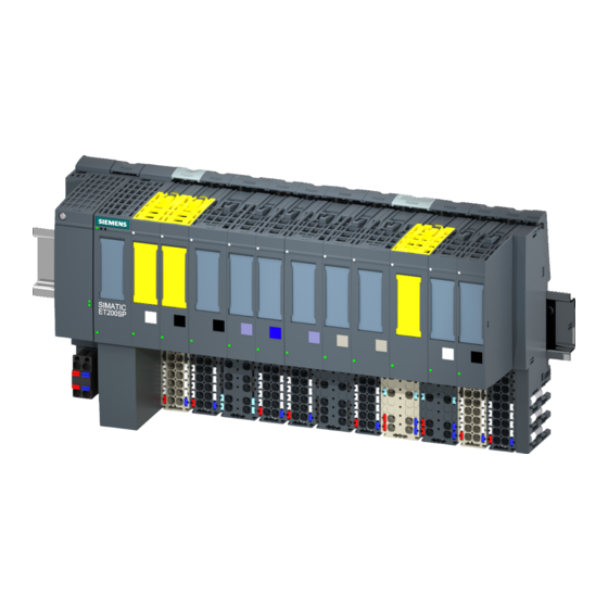
View of the Module
Visual representation of the interface module and server module.
Maximum Configuration
Specifies the limits for I/O modules and I/O data for the system.
Accessories
Lists optional accessories that can be ordered separately for the interface module.
Server Module
Describes the properties and function of the server module included with the interface module.
Functions
Lists the PROFINET IO and additional functions supported by the interface module.
Isochronous Real-time Communication
Explains the synchronized transmission method for IRT data exchange between PROFINET devices.
Prioritized Startup
Describes the PROFINET IO functionality for accelerating the startup of IO devices.
Device Replacement
Details scenarios for replacing the interface module with and without topological configuration.
Replacement Scenario of an IM 155-6 PN ST
Outlines the procedure for replacing an operational IO device in the system.
Media Redundancy (MRP)
Explains the function for safeguarding communication and plant availability via ring topology.
Shared Device
Describes how an IO device makes its data available to multiple IO controllers.
Module-Internal Shared Input/Shared Output (MSI/MSO)
Allows input/output modules to share data with up to two IO controllers.
Value Status
Indicates that the interface module supports I/O modules with value status (Quality Information).
PROFlenergy
Reduces energy consumption using PROFlenergy commands during non-production periods.
Configuration Control (Option Handling)
Enables preparing the distributed I/O system for future extensions or changes via user program.
Connecting
Terminal Assignment
Shows the pin assignment for the 24 V DC supply voltage connection.
PROFINET IO with BusAdapter BA 2×RJ45
Details the pin assignment for the PROFINET IO connection using the RJ45 BusAdapter.
PROFINET IO with BusAdapter BA 2×FC
Details the pin assignment for the PROFINET IO connection using the FC BusAdapter.
Schematic Circuit Diagram
Presents a block diagram illustrating the interface module's internal structure and connections.
Parameters/Address Space
Parameters
Lists parameters for the IM 155-6 PN ST interface module as per the GSD file.
Explanation of Parameters
Provides detailed explanations for the configurable parameters of the interface module.
Configuration Control
Explains the "Configuration control" parameter for enabling system flexibility.
Substitute Value Behavior
Describes how the system handles substitute values when modules are unavailable or errors occur.
Status of the Supply Voltage L+ of the I/O Modules
Details how to read the status of the supply voltage L+ for I/O modules via input data.
Interrupts, Diagnostics, Error, and System Messages
Status and Error Displays
Explains the LED displays on the interface module and BusAdapter for status and errors.
Meaning of the LEDs
Provides a detailed breakdown of the RN/ER/MT LED status and error indications and their remedies.
PWR LED on the Interface Module
Explains the status display of the PWR LED on the interface module and its remedy.
LK1/LK2 LED on the BusAdapter
Explains the status display of the LK1/LK2 LEDs on the BusAdapter and their remedy.
LED Display of Configuration Errors
Identifies configuration errors indicated by the ERROR and MAINT LEDs.
Principle of Operation
Describes how to determine error causes using LED displays and error code sequences.
Error Display
Lists possible error causes and their remedies based on error type and location.
Interrupts
Explains how the I/O device generates and evaluates interrupts based on error events.
Evaluating Interrupts with I/O Controllers
Lists the types of interrupts supported by the ET 200SP system and their handling.
System Diagnostics
Describes the availability and use of updated system diagnostics in STEP 7 (TIA Portal).
Triggering of a Diagnostics Interrupt
Explains how channel events trigger diagnostics interrupts and their processing.
Triggering a Hardware Interrupt
Describes how process interrupts trigger hardware interrupts and their handling.
Triggering a Swapping Interrupt
Explains how swapping interrupts are triggered and processed by the CPU.
Alarms
Details actions taken after a diagnostics alarm, including LED flashing and OB calls.
Actions After a Diagnostics Alarm
Lists the specific actions initiated by each diagnostics alarm on the interface module.
Reading the Diagnostics
Explains how to read diagnostic data using STEP 7 and specific instructions.
Additional Information on Data Records for PROFINET IO
Points to resources for diagnostic data record structures and programming examples.
Causes of Error and Troubleshooting
Refers to product manuals for causes and remedies of diagnostics alarms.
Maintenance Events
Describes maintenance events that signal when network components need checking or replacement.
Triggering of a Maintenance Event
Explains how the interface module signals maintenance events, like synchronization loss.
System Events in STEP 7 (TIA Portal)
Details how maintenance information is generated as system events in STEP 7.
Channel Diagnostics
Provides information about channel faults and how they are mapped as diagnostics data.
Structure of the Diagnostics Data Records
Explains the structure of data records based on the PROFINET IO standard.
Structure of Manufacturer-Specific Diagnostics Data Records
Details the structure of diagnostics data records differentiated by BlockVersion for the interface module.
Manufacturer-Specific Diagnostics in the User Structure Identifier (USI)
Lists manufacturer-specific diagnostics data signaled in the USI for the interface module.
USI Structure = W#16#0003
Defines the USI structure for diagnostics related to supply voltage L+ failure.
USI Structure = W#16#0004
Defines the USI structure for diagnostics related to a missing server module.
USI Structure = W#16#0005
Defines the USI structure for diagnostics indicating more than one I/O module has been pulled.
USI Structure = W#16#0006
Defines the USI structure for diagnostics of an I/O module installed on an incorrect BaseUnit.
USI Structure = W#16#0007
Defines the USI structure for diagnostics when operation is not possible with existing bus configuration.
Invalid Configuration States of the ET 200SP on PROFINET IO
Lists invalid configuration states that cause IO device failure or prevent data exchange.
Failure of Supply Voltage L+ at BaseUnit BU...D
Explains how I/O modules react to the failure of supply voltage L+ on the BaseUnit.
STOP of the IO Controller and Recovery of the IO Device
Details how to handle diagnostics when the IO controller is in STOP mode and how to recover IO devices.
Compatibility
GSD File
Describes the use of different GSD files with interface modules and their changes.
Status of the Supply Voltage
Notes that load voltage diagnostics are valid only after a complete startup with valid configuration.
First BaseUnit of an ET 200SP in Configuration (as of V3.1)
Provides guidance on the type of BaseUnit to use as the first unit in the configuration.
Value Status (Quality Information, QI)
Lists I/O modules that can evaluate value status (Quality Information).
Reaction Times for Fail-Safe Modules
States the maximum reaction time of the interface module for fail-safe module calculations.
Fail-Safe Modules Are Not Compatible Replacement Parts
Highlights incompatibility of certain fail-safe modules as replacement parts and the need for re-configuration.
Technical Specifications
Technical Specifications of the IM 155-6 PN ST
Provides comprehensive technical specifications for the IM 155-6 PN ST interface module.
Interfaces
Details the PROFINET interfaces, hardware, protocols, and services of the module.
RJ45 (Ethernet)
Specifies Ethernet transmission speeds, methods, and protocols supported by the interface.
PROFINET IO
Lists PROFINET IO device services such as IRT, PROFlenergy, Shared device.
Interrupts/Diagnostics/Status Information
Covers status display, interrupts, diagnostic alarms, and LED indicators.
Galvanic Isolation
Details the galvanic isolation properties between different circuits of the module.
Standards, Approvals, Certificates
Lists applicable standards, network loading class, and security levels.
Dimensions
Provides the physical dimensions (width, height, depth) of the interface module.
Weights
Specifies the approximate weight of the interface module.
Technical Specifications of the BusAdapter BA 2×RJ45
Lists the technical specifications for the RJ45 BusAdapter.
Technical Specifications of the BusAdapter BA 2×FC
Lists the technical specifications for the FC BusAdapter.
Dimensional Drawing
Dimensional Drawing of the IM 155-6 PN ST Interface Module (Front and Side View)
Provides a dimension drawing of the interface module for installation purposes.
Need help?
Do you have a question about the 6ES7155-6AU00-0BN0 and is the answer not in the manual?
Questions and answers