Table of Contents
Advertisement
Advertisement
Table of Contents

Related Manuals for Siemens 6ES7136-6CB00-0CA0


Summarization of Contents
Documentation Guide
1.1 ET 200SP Documentation Guide
Details the structure of the SIMATIC ET 200SP distributed I/O system documentation.
Product Overview
2.1 Properties
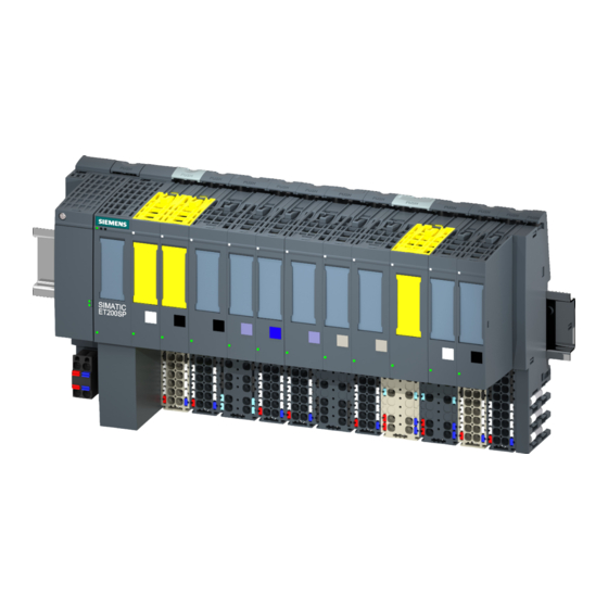
Describes the article number, firmware version, and physical view of the module.
2.2 Functions
Details the various functions the F-TM Count module offers, including safety features.
Connecting
3.1 Wiring and Block Diagram
Provides the wiring and block diagram for the F-TM Count module.
Parameters/Address Space
4.1 Configuring the F-TM Count Module
Explains how to configure the module's operating properties using STEP 7 Safety.
4.2 Reinitialize on Parameterization Download
Describes the module's reinitialization process during parameterization.
4.3 Reaction to CPU STOP
Defines the module's response when the F-CPU enters STOP mode.
4.4 Reactions to Counting Limit Violation
Explains how the module reacts when counting limits are violated.
4.5 Parameters of the F-TM Count
Lists and details settable parameters for the F-TM Count module.
4.6 Explanation of Parameters
Provides detailed explanations for various F-parameters and TM-C parameters.
4.8 Quadrature Evaluation of Differential Signals
Explains how the module evaluates quadrature encoded signals from encoders.
4.9 Safety Functions
Overview of the module's safety functions like SOS, SLS, and SDI.
4.10 Address Space
Details the input and output address space for the F-TM Count module.
4.11 Control and Feedback Interface
Explains the interface for controlling module behavior and receiving status.
Applications of the F-I/O Module
5.1 Application Mode 1: A/B with N
Describes the A/B with N signal configuration for encoders.
5.2 Application Mode 2: A/B without N
Describes the A/B without N signal configuration for encoders.
Interrupts/Diagnostic Messages
6.1 Reactions to Faults
Explains how the system reacts to faults, including passivation and reintegration.
6.2 Status and Error Display
Details the meaning of the module's LEDs for status and error indication.
6.3 Interrupts
Provides an overview of diagnostic interrupts generated by the F-module.
6.4 Diagnostic Messages
Lists diagnostic alarms, their meanings, fault codes, and possible solutions.
6.5 Value Status (CQ HSCO)
Explains the value status bit providing information on process input validity.
Technical Specifications
7.1 Specifications
Lists detailed technical data, electrical properties, and environmental conditions.
Response Times
A.1 Maximum Response Time of the System
Explains how to calculate the overall system response time.
A.2 Response Times of the F-TM Count Module
Details specific response times for the F-TM Count module inputs and faults.
Parameter Data Record
B.1 Parameter Defaults and Dependencies When Configuring with GSD File
Lists default parameter settings and their interdependencies for configuration.
Need help?
Do you have a question about the 6ES7136-6CB00-0CA0 and is the answer not in the manual?
Questions and answers