Table of Contents
Advertisement
Quick Links
Technical information
Installation instructions
UltraGas
2 (125-1550)
®
Gas condensing boilers
for natural gas in modulating operation
Hoval products must be installed and commissioned by
specialists only. These instructions are intended exclu-
sively for the specialist. Electrical installation must be
performed by a licensed electrical company.
Subject to modifi cations
|
4 220 950 / 00 - 04/22
These instructions are applicable to the fol-
lowing types:
Nominal output ranges at 50/30 °C
and natural gas
52-UltraGas
®
52-UltraGas
®
52-UltraGas
®
52-UltraGas
®
52-UltraGas
®
52-UltraGas
®
52-UltraGas
®
52-UltraGas
®
52-UltraGas
®
52-UltraGas
®
52-UltraGas
®
52-UltraGas
®
52-UltraGas
®
52-UltraGas
®
52-UltraGas
®
52-UltraGas
®
52-UltraGas
®
52-UltraGas
®
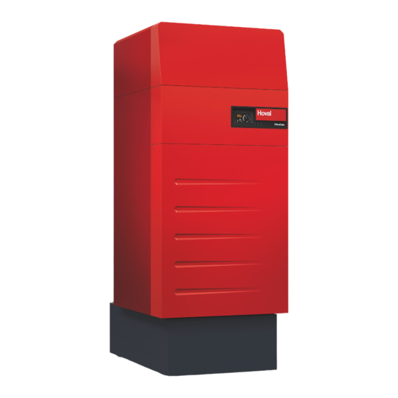
Floor-standing gas condensing boilers UltraGas
(125-1550) acc. to EN 15502-1/15502-2-1 are suitable
and licensed for use as heat generators for hot water
heating systems with a permissible flow temperature of
up to 95 °C
. They are designed for continuously con-
1)
trolled reduced operation in heating systems.
See technical data
1)
2 (125)
25-126 kW
2 (150)
35-151 kW
2 (190)
38-191 kW
2 (230)
51-233 kW
2 (300)
58-299 kW
2 (350)
70-352 kW
2 (400)
69-399 kW
2 (500)
77-491 kW
2 (530)
110-533 kW
2 (620)
136-622 kW
2 (700)
146-703 kW
2 (800)
166-804 kW
2 (1000)
205-999 kW
2 (1100)
229-1112 kW
2 (1300)
269-1320 kW
2 (1550)
324-1550 kW
2 H (1100)
229-1112 kW
2 H (1550)
324-1550 kW
EN
®
2
Advertisement
Table of Contents

Related Manuals for Hoval 52-UltraGas 2 150


Summarization of Contents
Important Notices and General Safety
System Manual and Information Sources
Details on the system manual and other sources of information.
General Safety Instructions and Warnings
Covers personnel qualification, gas hazards, hot surfaces, and filling water notices.
Important Notices and Explanation of Symbols
Handling Cautions and Electrical Safety
Cautions on sharp edges, de-energizing, and electrical circuit safety.
Warning Symbols and Hazard Definitions
Defines DANGER, WARNING, CAUTION, NOTICE and their associated symbols.
Important Notices: Information and Guarantee
Information Symbols and Delivery Checks
Explains information symbols and procedures for checking delivery.
Guarantee Terms and Conditions
Outlines conditions under which the guarantee does not cover defects.
Regulations, Standards, and Directives
Applicable Regulations and Standards by Country
Lists country-specific regulations, standards, and directives for heating systems.
Technical Information: Product Description
UltraGas® 2 Boiler Components and Fuels
Describes the UltraGas® 2 boiler, its components, and approved fuels.
Technical Information: Function Descriptions
BIC 970 Automatic Function Device Details
Brief description of the BIC 970 device, its inputs, outputs, and fuses.
Technical Information: Data Plate Explained
Meaning of Data Plate Information Fields
Explains the meaning of various data fields on the product data plate.
Technical Data: UltraGas® 2 (125-1550) Specifications
Technical Data Overview (Models 125-230)
Presents detailed technical specifications for UltraGas® 2 models 125 to 230.
Technical Data: UltraGas® 2 (300-500) Specifications
Technical Data Overview (Models 300-500)
Presents detailed technical specifications for UltraGas® 2 models 300 to 500.
Technical Data: UltraGas® 2 (530-800) Specifications
Technical Data Overview (Models 530-800)
Presents detailed technical specifications for UltraGas® 2 models 530 to 800.
Technical Data: UltraGas® 2 (1000-1550) Specifications
Technical Data Overview (Models 1000-1550)
Presents detailed technical specifications for UltraGas® 2 models 1000 to 1550.
Technical Data: UltraGas® 2 H (1100, 1550) Specifications
Technical Data Overview (Models 1100, 1550 H)
Presents detailed technical specifications for UltraGas® 2 H models 1100 and 1550.
Technical Data: Heating Water Flow Resistance
Flow Resistance Charts for UltraGas® 2 Models
Graphical representation of heating water side flow resistance for different UltraGas® 2 models.
Dimensions: UltraGas® 2 (125-1550) Overview
Unit Dimensions and Drawings
Provides dimensional drawings and a table of dimensions for UltraGas® 2 models.
Dimensions: Overall Unit and Component Weights
Weight and Installation Space Requirements
Details weights of components and minimum door/corridor widths for installation.
Dimensions: Space Requirements
Installation Space Requirements for UltraGas® 2
Specifies minimum installation space requirements around the boiler, including clearance for burner swing-out.
Dimensions: Installation Variants
Reduced Height Installation Options
Illustrates installation variants with reduced height requirements using masonry base.
Installation: Setting Up the Heat Generator
Boiler Room Requirements and Location
Specifies requirements for the boiler room, including combustion air and halogen compound avoidance.
Safe Boiler Suspension Method
Details the correct method for suspending the boiler using provided points.
Installation: Setting Up UltraGas® 2 (125,150)
Step-by-Step Boiler Setup Procedure
Provides instructions for setting up the UltraGas® 2 (125,150) boiler from its pallet.
Installation: Setting Up UltraGas® 2 (190-1550)
Setup Procedure for Larger UltraGas® 2 Models
Details the setup process for UltraGas® 2 models from 190 to 1550.
Installation: Thermal Insulation
Applying Boiler Insulation Mats Correctly
Instructions on how to place and secure the insulation mat around the boiler.
Installation: Mounting Cladding Sections
Cladding Sequence for UltraGas® 2 (125-1100)
Lists the sequence for mounting cladding sections for UltraGas® 2 (125-1100).
Installation: Mounting Cladding Sections
Cladding Sequence for UltraGas® 2 (1300-1550)
Lists the sequence for mounting cladding sections for UltraGas® 2 (1300-1550).
Installation: Cladding Assembly Details
Installing Cable Ducts and Side Walls
Instructions for installing cable ducts and side wall sections.
Installation: Cladding Assembly Details
Installing Electrical Box and Rear Wall
Guides on installing the electrical box and rear wall sections of the cladding.
Installation: Cladding Assembly Details
Installing Side Walls and Upper Rear Wall
Instructions for installing upper side walls and the upper rear wall sections.
Installation: Cladding Assembly Details
Installing Front Cover and Base Cladding
Details for installing the front cover plate, base cladding, and front cover.
Installation: Removing Cladding Components
Removing Front Cover and Upper Front Panels
Step-by-step guide for removing the front cover and upper front sections of the cladding.
Installation: Removing Cladding Components
Removing Upper Rear Wall and Side Panels
Instructions for removing upper rear wall sections and upper side walls.
Installation: Combustion Air Supply
Room Air Dependent Installation Requirements
Notes on regulations for room air dependent installation.
Room Air Independent Installation Requirements
Requirements for room air independent installation with separate combustion air line.
Installation: Flue Gas Connection and Lines
Flue Gas Line Directives and Dimension Calculation
Directives for flue gas evacuation and calculation of flue gas line dimensions.
Installation: Flue Gas Line Dimensions
Standard Values for Flue Gas Line Dimensions
Table of standard values for flue gas line dimensions based on bends and length.
Installation: Combustion Air/Flue Gas Ducting
Combustion Air/Flue Gas Ducting Design Variants
Illustrates design variants for combustion air and flue gas ducting (B23, C53, C63).
Installation: Condensate Drain System
Condensate Drain Engineering Guidelines
Guidelines for condensate drain installation, materials, and requirements.
Installation: Condensate Drain Discharge
Sewer Discharge and Pre-Commissioning Checks
Notes on sewer discharge, germ contamination, and siphon filling before commissioning.
Installation: Condensate Drain Siphon Setup
Standard Sewer System Condensate Connection
Instructions for installing siphon and condensate drain to a standard sewer system.
Condensate Pump Sewer System Connection
Instructions for installing siphon and condensate drain with a condensate pump for higher level sewer systems.
Installation: Condensate Drain with Neutralisation
Sewer System with Neutralisation Unit Setup
Installation of siphon, neutralisation unit, and drain to sewer system.
Sewer System with Pump and Neutralisation Setup
Installation of siphon, pump, neutralisation unit, and drain to sewer system.
Installation: Gas Connection Procedures
Gas Connection Safety and Component Requirements
Safety precautions, regulations, and required components for gas connection.
Installation: Gas Connection Procedures
Venting Gas Pipe and Pre-Operation Checks
Procedure for venting the gas pipe and necessary checks before heat generator operation.
Installation: Hydraulic Connection Principles
Safety Equipment and Required Components
Details safety devices integrated in the boiler and required customer-installed components.
Installation: Hydraulic Integration Guidelines
General Hydraulic Connection Guidelines
General rules for hydraulic connection, safety valve, pressure limiters, and heating pump.
Installation: Hydraulic Integration Specifics
Attic, Calorifier, and Underfloor Heating Integration
Specific notes for heat generator installation in attics, calorifiers, and underfloor heating.
Heat Generator Cascade System Integration
Guidelines for operating multiple heat generators in a cascade system.
Installation: Heating Water Quality (Germany/Austria)
Water Quality Standards for Germany and Austria
Specifies water quality standards for heating systems in Germany and Austria.
Installation: Heating Water Quality (Switzerland)
Water Quality Standards for Switzerland
Specifies water quality standards for heating systems in Switzerland.
Installation: Filling the Heating System
Heating System Filling and Pressure Check Procedure
Step-by-step guide for filling the heating system with water and checking pressure.
Installation: Electrical Connection Procedure
Removing Front Cladding for Electrical Access
Procedure for removing front cladding to access electrical connections.
Installation: Electrical Connection Safety (EMC)
EMC Precautions and Cable Routing Rules
Safety precautions for electrical installation regarding EMC, cable routing, and distances.
Installation: Electrical Connection Safety (EMC)
Equipotential Bonding and Data Bus Network EMC
Guidelines for equipotential bonding, data bus networks, and avoiding interference.
Installation: Electrical Cable Recommendations
Recommended Cable Cross-sections and Lengths
Table listing recommended cable cross-sections and maximum permitted lengths for various line types.
Commissioning: Prerequisites for Trial Operation
Required Conditions for Trial Operation Start
Lists the necessary conditions that must be met before initiating trial operation.
Commissioning: Installation Inspection and Settings
Installation Inspection and Parameter Checks
Steps for performing an installation inspection and checking parameter settings.
Commissioning: Heat Generator Startup and Pressure Checks
Heat Generator Startup Procedure
Procedure for switching the heat generator on.
Gas Flow Pressure Checking Procedure
Steps to check the gas flow pressure and its permissible range.
Commissioning: Gas Quantity and Flue Gas Analysis
Flue Gas Measurement for UltraGas® 2 (125-700)
Procedure for setting gas quantity and measuring O₂, CO₂, NOx/CO in flue gas for models 125-700.
Commissioning: Flue Gas Analysis (800-1550)
Flue Gas Measurement for UltraGas® 2 (800-1550)
Procedure for setting gas quantity and measuring O₂, CO₂, NOx/CO in flue gas for models 800-1550.
Commissioning: Final Checks and Handover
Pre-Handover Monitoring and Checks
Checks for combustion air, flue gas tightness, gas tightness, and condensate drain before handover.
Maintenance: Routine Tasks and Safety
General Maintenance Tasks and Procedures
Lists routine maintenance tasks including bleeding, water top-up, and cleaning.
Maintenance: Heating System Servicing
Bleeding the Heating System Instructions
Procedure for bleeding radiators and underfloor heating circuits.
Replenishing Replacement Water Guidelines
Guidelines for replenishing replacement water based on pressure drops.
Maintenance: Emission and Manual Operation Settings
Emission Metering Settings for Fire Inspectors
Information for fire inspectors on emission metering settings and reaction.
Manual Operation Settings for Heating Circuits
Information on manual operation settings and reaction for heating or hot water circuits.
Maintenance: Heat Generator Cleaning Procedures
Disconnecting Gas and Removing Cladding
Steps to disconnect gas and remove cladding for cleaning.
Maintenance: Heat Generator Cleaning Procedures
Checking and Removing the Burner Cylinder
Procedure for checking, cleaning, and removing the burner cylinder.
Maintenance: Heat Generator Cleaning Procedures
Cleaning Ignition/Ionisation Devices and Combustion Chamber
Instructions for cleaning ignition/ionisation devices and the combustion chamber.
Maintenance: Heat Generator Cleaning Procedures
Cleaning Drip Tray, Siphon, and Cleaning Opening
Steps for cleaning the condensate drip tray, siphon, and cleaning opening.
Maintenance: Neutralisation Unit and Condensate Drain
Maintaining Neutralisation Unit and Condensate Drain
Procedures for maintaining the neutralisation unit and checking the condensate drain.
Maintenance: Gas Connection and Pressure Checks
Replacing Seals and Connecting Gas
Instructions for replacing seals, connecting gas, and checking screw connections.
Maintenance: Final Checks and Measurements
Flue Gas Measurement and Final Checks
Carrying out flue gas measurement and final checks before recommissioning.
Maintenance: Motorised Combustion Air Damper Servicing
Servicing the Motorised Combustion Air Damper
Instructions for servicing the optional motorised combustion air damper.
Maintenance: Motorised Combustion Air Damper Servicing
Lubricating Motor Bearings and Damper Movement
Steps for lubricating motor bearings and moving the motorised combustion air damper.
Maintenance: Motorised Combustion Air Damper Installation
Installing Motorised Air Dampers and Electrical Connection
Procedure for installing motorised air dampers and connecting them electrically.
Maintenance: Fuse Replacement and Final Checks
Renewing the Fuse Safely
Instructions for safely replacing the fuse in the heat generator.
Monitoring Before Handover to Operator
Final checks to be performed before handing over the heat generator to the operator.
Appendix: Parameter List Introduction
BIC 970 Automatic Function Device Parameters
Table listing parameters for the BIC 970 automatic function device for UltraGas® 2.
Appendix: Parameter List Details
Detailed Parameter Settings for UltraGas® 2 Models
Continues the table of parameters for various UltraGas® 2 models.
Appendix: Screed Function Description
Activating and Setting the Screed Function
Describes the screed function and its parameters for drying screed floors.
Appendix: Screed Function Control Module Settings
TopTronic® E Control Module Screed Settings
Details settings within the TopTronic® E control module for the screed function.
Need help?
Do you have a question about the 52-UltraGas 2 150 and is the answer not in the manual?
Questions and answers