Table of Contents
Advertisement
SERVICE MANUAL
Ver. 1.0 2011.03
• HCD-GZR888DA/GZR999DA are the tuner,
deck, DVD and amplifi er section in MHC-
GZR888DA/GZR999DA.
Amplifi er section
The following measured at AC 127 V, 60 Hz
(Mexican model)
The following measured at AC 120 V, 220 V,
240 V, 50/60 Hz (Other models)
MHC-GZR999DA
Power output (rated):
135 W + 135 W (at 6 Ω, 1 kHz, 1%
THD, at LINK MODE)
RMS output power (reference)
Front speaker:
210 W + 210 W (per channel at 8 Ω,
1 kHz)
Satellite speaker:
90 W + 90 W (per channel at 24 Ω,
1 kHz)
Subwoofer:
240 W (at 6 Ω, 100 Hz)
• Abbreviation
E2
: 120V AC area in E model
E3
: 240V AC area in E model
E4
: 110 – 120V/220 – 240V AC area in E model
E51
: Chilean and Peruvian models
MX
: Mexican model
PH
: Philippines model
SP
: Singapore model
9-893-138-01
Sony Corporation
2011C04-1
©
2011.03
Published by Sony Techno Create Corporation
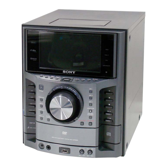
Photo: HCD-GZR999DA
Model Name Using Similar Mechanism
DVD
DVD Mechanism Type
Section
Optical Pick-up Name
Model Name Using Similar Mechanism
Tape Deck
Section
Tape Transport Mechanism Type
SPECIFICATIONS
MHC-GZR888DA
Power output (rated):
125 W + 125 W (at 6 Ω, 1 kHz, 1%
THD, at LINK MODE)
RMS output power (reference)
Front speaker:
210 W + 210 W (per channel at 8 Ω,
1 kHz)
Satellite speaker:
90 W + 90 W (per channel at 24 Ω,
1 kHz)
HCD-GZR888DA/GZR999DA: E3, E4, PH, SP Model
HCD-GZR888DA/
GZR999DA
HCD-GZR777DA
CDM74HFVX-DVBU101
KHM-313CAB
HCD-GZR777DA
CFP42608
– Continued on next page –
DVD DECK RECEIVER
HCD-GZR999DA: E2, E51, MX Model
DVD RECEIVER
E Model
Advertisement
Table of Contents

Related Manuals for Sony HCD-GZR999DA


Summarization of Contents
Product Specifications
Amplifier Power Output Ratings
Lists rated and RMS power for MHC-GZR999DA and MHC-GZR888DA.
System Overview and Safety Information
General Unit Specifications
Covers power requirements, consumption, dimensions, and mass.
Safety-Related Component Warning
Identifies critical components for safe operation.
Critical Servicing Notes
Chip Component Replacement Precautions
Guidelines for replacing chip components, particularly tantalum capacitors.
Laser Diode Emission Check Safety
Precautions for checking laser diode emission to avoid radiation exposure.
Service Manual Sections
Servicing Notes
General notes and precautions for servicing the unit.
Disassembly Procedures
Detailed steps for disassembling unit components.
Test Modes
Procedures for entering and utilizing diagnostic test modes.
Mechanical Adjustments
Procedures and specifications for mechanical adjustments.
Electrical Adjustments
Procedures and specifications for electrical adjustments.
Diagrams and Board Layouts
Overview of block diagrams, schematics, and board layouts.
Exploded Views
Visual breakdown of unit parts with references.
Electrical Parts List
Comprehensive list of electronic components.
Need help?
Do you have a question about the HCD-GZR999DA and is the answer not in the manual?
Questions and answers