Table of Contents
Advertisement
QQ
3 7 63 1515 0
SERVICE MANUAL
Ver 1.0 2003.04
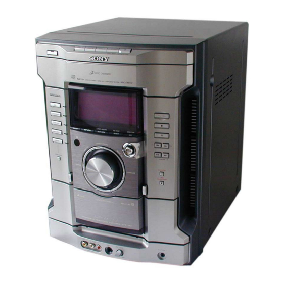
HCD-GN600 is the amplifier, CD player,
tape deck and tuner section in MHC-
GN600.
TE
L 13942296513
Amplifier section
The following are measured at AC 127V, 60 Hz (Mexican model only)
The following are measured at AC 120, 220, 240V50/60 Hz
(except Mexican model)
DIN power output (rated)
Continuous RMS power output (reference)
Inputs
GAME (VIDEO):
(phono jack)
GAME (AUDIO):
(phono jacks)
MD/VIDEO (AUDIO) IN:
(phono jacks)
MIC:
(phone jack)
Outputs
VIDEO OUT:
(phono jacks)
PHONES:
(stereo mini jack)
FRONT SPEAKER:
www
.
Sony Corporation
9-877-282-01
2003D0200-1
Home Audio Company
C 2003.04
Published by Sony Engineering Corporation
http://www.xiaoyu163.com
Model Name Using Similar Mechanism
CD Mechanism Type
CD
Section
Base Unit Name
Optical Pick-up Name
Model Name Using Similar Mechanism
TAPE
Section
Tape Transport Mechanism Type
130 + 130 watts
(6 ohms at 1 kHz, DIN)
165 + 165 watts
(6 ohms at 1 kHz, 10% THD)
1 Vp-p, 75 ohms
Voltage 250 mV,
impedance 47 kilohms
voltage 450 mV/250 mV,
impedance 47 kilohms
sensitivity 1 mV,
impedance 10 kilohms
max. output level 1 Vp-p,
unbalanced, Sync.
negative load impedance 75 ohms
accepts headphones of
8 ohms or more
accepts impedance of 6 to
16 ohms
x
ao
u163
y
i
http://www.xiaoyu163.com
HCD-GN600
2 9
8
Q Q
3
6 7
1 3
1 5
SPECIFICATIONS
CD player section
System
Laser
Laser Output
Frequency response
Wave length
CD OPTICAL DIGITAL OUT
(Square optical connector jack, rear panel)
Wave length
Output Level
Tape player section
Recording system
Frequency response
MiNi Hi-Fi COMPONENT SYSTEM
co
.
9 4
2 8
E Model
NEW
CDM74-K6BD47S
BU-K6BD47S
KSM-213DCP
HCD-XGR88
CWM43RR23
0 5
8
2 9
9 4
2 8
Compact disc and digital audio system
Semiconductor laser
(λ=795nm)
Max. 44.6 µW*
*This output is the value measured at a
distance of 200 mm from the objective lens
surface on the Optical Pick-up Block with 7
mm aperture.
2 Hz – 20 kHz (±0.5 dB)
795 nm
660 nm
–18 dBm
4-track 2-channel stereo
50 – 13,000 Hz (±3 dB),
using Sony TYPE I cassette
– Continued on next page –
m
9 9
9 9
Advertisement
Table of Contents

Related Manuals for Sony HCD-GN600


Summary of Contents for Sony HCD-GN600
- Page 1 HCD-GN600 3 7 63 1515 0 SERVICE MANUAL E Model Ver 1.0 2003.04 HCD-GN600 is the amplifier, CD player, tape deck and tuner section in MHC- GN600. Model Name Using Similar Mechanism CD Mechanism Type CDM74-K6BD47S Section Base Unit Name...
- Page 2 LINE WITH MARK 0 ON THE SCHEMATIC DIAGRAMS AND IN THE PARTS LIST ARE CRITICAL TO SAFE OPERATION. REPLACE THESE COMPONENTS WITH SONY PARTS WHOSE PART NUMBERS APPEAR AS SHOWN IN THIS MANUAL OR IN SUPPLEMENTS PUB- LISHED BY SONY.
-
Page 3: Table Of Contents
HCD-GN600 3 7 63 1515 0 TABLE OF CONTENTS SERVICING NOTES 7-14. Schematic Diagram – Display Board – ......43 ..........4 7-15. Printed Wiring Board – Power Amp Board – ....44 7-16. Schematic Diagram – Power Amp Board – ....45 GENERAL 7-17. -
Page 4: Servicing Notes
HCD-GN600 SECTION 1 SERVICING NOTES 3 7 63 1515 0 • MODEL IDENTIFICATION NOTES ON HANDLING THE OPTICAL PICK-UP – Back Panel – BLOCK OR BASE UNIT The laser diode in the optical pick-up block may suffer electro- PART No. -
Page 5: General
HCD-GN600 SECTION 2 This section is extracted from instruction manual. 3 7 63 1515 0 GENERAL Main unit ALPHABETICAL ORDER GAME INPUT (jacks) wj A - D R - Z GAME MIXING ef REC PAUSE/START qk ALBUM +/- qg... -
Page 6: Remote Control
HCD-GN600 This section is extracted from instruction manual. 3 7 63 1515 0 Remote Control ALPHABETICAL ORDER TUNING + ws A - M VOL +/- 8 CD ql CLEAR 7 SYMBOLS CLOCK/TIMER SELECT 2 @/1 (power) 4 CLOCK/TIMER SET 3... -
Page 7: Disassembly
HCD-GN600 SECTION 3 DISASSEMBLY 3 7 63 1515 0 • This set can be disassembled in the order shown below. CASE LOADING (PANEL) FRONT PANEL ASSY TUNER PACK, GAME IN BOARD, CD MECHANISM DECK SUB TRANS BOARD TAPE MECHANISM DECK... - Page 8 HCD-GN600 3 7 63 1515 0 Note: Follow the disassembly procedure in the numerical order given. 3-1. CASE 2 Five screws (+BVTT3 x 6) 6 Case 1 Three screws (case 3 TP2) 3 Two screws (+BVTT3 x 6) 1 Three screws...
- Page 9 HCD-GN600 3 7 63 1515 0 3-3. FRONT PANEL ASSY 8 Front panel ASSY 3 Screw (BVTP3 x 10) 1 Two wires (flat type) 7 From CN607 on Game in board MAIN board CN402 CN304 4 From deck B head...
- Page 10 HCD-GN600 3 7 63 1515 0 3-5. CD MECHANISM DECK 2 Wire (flat type) (31 core) 4 CD mechanism deck 1 Two screws (BVTP3 x 10) CN201 3 CN701 MAIN board L 13942296513 3-6. GAME IN BOARD, TAPE MECHANISM DECK 2 Screw (+PTT2 x 4) 4 Two screws (+BVTP2.6 x 8)
-
Page 11: Volume Board
HCD-GN600 3 7 63 1515 0 3-7. CD SWITCH BOARD, DISPLAY BOARD 1 Six screws 4 Five screws (+BVTP2.6 x 8) (+BVTP2.6 x 8) 2 CD SWITCH board 5 DISPLAY board 4 Five screws (+BVTP2.6 x 8) 3 Wire (flat type) (17 core) -
Page 12: Main Board
HCD-GN600 3 7 63 1515 0 3-9. REAR PANEL 6 rear panel with fan 1 two screws (+BVTT3 x 6) 2 two screws (+BVTP3 x 10) 3 three screws (+BVTP3 x 10) 4 three screws (+BVTP3 x 10) 5 connector... -
Page 13: Power Amp Board
HCD-GN600 3 7 63 1515 0 3-11. POWER AMP BOARD 4 Two screws (+BVTP3 x 10) 6 Two screws (+BVTP3 x 10) 3 Bracket (HS) 5 Three screws (+BVTP3 x 10) 2 Two screws (+BVTP3 x 10) 7 POWER AMP board... -
Page 14: Cd Board, Cd Block Assy
HCD-GN600 3 7 63 1515 0 3-13. CD BOARD, CD BLOCK ASSY 3 Floating screw (+PTPWH M2.6) 1 Floating screw (+PTPWH M2.6) 6 Two insulators 2 Holder (213) ASSY qh CD block ASSY 5 Two coil springs 0 Two insulators... -
Page 15: Motor (Tb) Board
HCD-GN600 3 7 63 1515 0 3-15. MOTOR (TB) BOARD 6 Table motor ASSY (M741) 2 CN742 (flat type) 4 MOTOR (TB) board 5 Remove the two solderings of motor. 3 Two screws (+BTTP (M2.6)) L 13942296513 3-16. MOTOR (LD) BOARD 2 Two screws (+BTTP (M2.6)) -
Page 16: Test Mode
HCD-GN600 SECTION 4 TEST MODE 3 7 63 1515 0 [GC TEST MODE] * Check of Amplifier • This mode is used to check the fluorescent indicator tube, LED, 1. When button is pressed, GEQ increases to its maximum and model, destination, software version, volume, key and VACS a message “GEQ MAX”... - Page 17 HCD-GN600 3 7 63 1515 0 [COLD RESET] [AGING MODE] • The cold reset clears all data including preset data stored in the This mode can be used for operation check of CD section. RAM to initial conditions. Execute this mode when returning •...
- Page 18 HCD-GN600 3 7 63 1515 0 • Display when an error occurred (CD Error Code Mode) 3) Display of no disc errors Procedure: Display [AMP MENU] [DISC 1] 1. Press button, button and button simultaneously to enter the error code display mode.
- Page 19 HCD-GN600 3 7 63 1515 0 [CD SHIP MODE (WITHOUT MEMORY CLEAR)] [CD TRAY LOCK MODE] • This mode moves the optical pick-up to the position durable to • This mode let you lock the disc trays. When this mode is vibration.
-
Page 20: Mechanical Adjustments
HCD-GN600 SECTION 5 SECTION 6 3 7 63 1515 0 MECHANICAL ADJUSTMENTS ELECTRICAL ADJUSTMENTS Precaution DECK SECTION 0 dB=0.775 V 1. Clean the following parts with a denatured alcohol-moistened swab: 1. Demagnetize the record/playback head with a head record/playback heads pinch rollers demagnetizer. - Page 21 HCD-GN600 3 7 63 1515 0 2. Turn the adjustment screw and check output peaks. If the peaks REC BIAS ADJUSTMENT DECK B do not match for L-CH and R-CH, turn the adjustment screw so that outputs match within 1dB of peak.
-
Page 22: Cd Section
HCD-GN600 3 7 63 1515 0 REC LEVEL ADJUSTMENT DECK B CD SECTION Procedure: Note: In the MC test mode, the “REC memory mode” is convenient for 1. CD Block is basically designed to operate without adjustment. There- this adjustment. In the “REC memory mode” , when the REC starts fore, check each item in order given. - Page 23 HCD-GN600 3 7 63 1515 0 RFAC Level Check E-F Balance Check Connection: Connection: oscilloscope oscilloscope CD board CD board TP5 (RFAC) TP2 (TE) TP7 (DVC) – TP7 (DVC) – Procedure: Procedure: Connect an oscilloscope to test point TP5 (RFAC) and TP Connect an oscilloscpe to test point TP2 (TE) and TP7 (DVC) 7(DVC) on the CD board.
- Page 24 HCD-GN600 3 7 63 1515 0 Checking Location: – CD BOARD (SIDE B) – TP4 (FE) IC101 TP2 (TE) TP7 (DVC) TP5 (RFAC) IC104 IC103 L 13942296513 u163 http://www.xiaoyu163.com...
-
Page 25: Diagrams
HCD-GN600 SECTION 7 3 7 63 1515 0 DIAGRAMS Note on Schematic Diagram: Note on Printed Wiring Boards: • All capacitors are in µF unless otherwise noted. pF: µµF • X : parts extracted from the component side. 50 WV or less are not indicated except for electrolytics •... -
Page 26: Circuit Board Location
HCD-GN600 3 7 63 1515 0 7-1. CIRCUIT BOARD LOCATION TUNER PACK SUB TRANS board CD SWITCH board TRANS board POWER AMP board L 13942296513 SENSOR board CD board SW board MOTOR (TB) board MOTOR (LD) board DRIVER board... - Page 27 HCD-GN600 3 7 6 3 1 5 1 5 0 WAVEFORMS – MAIN BOARD – – CD BOARD – – DISPLAY BOARD – IC501 qa XC-OUT IC101 ra TE IC601 is X OUT 2.4Vp-p 3.0Vp-p 0.4Vp-p 32KHz VOL/DIV : 0.2V AC...
-
Page 28: Block Diagram - Cd Servo Section
HCD-GN600 3 7 6 3 1 5 1 5 0 7-2. BLOCK DIAGRAM – CD SERVO Section – OPTICAL PICK-UP DIGITAL SERVO BLOCK DIGITAL SIGNAL PROC. RF AMP (KSS-213DCP) IC103 IC101 IC201 RF AC OPTICAL OPTICAL RFAC D OUT OUT(CD) CD A+3.3V... - Page 29 HCD-GN600 3 7 6 3 1 5 1 5 0 – TUNER/TAPE DECK Section – IC303 AMS DETECT R-CH Q390, 398, 399 MUTE Q306,389 DECK-A AIN1 L – CH EQ OUT1 TAPE L-CH PB OUT1 MAIN/POWER TAI1 HEAD SECTION R –...
- Page 30 HCD-GN600 3 7 6 3 1 5 1 5 0 – MAIN/POWER Section – REC L-CH TUNER/TAPE DECK SECTION SPEANA J631 DISPLAY SECTION R-CH D130 PHONES FEED BACK INPUT SELECT SWITCH, J117 SWITCH TONE CONTROL, Q101 ELECTRICAL VOLUME HEADPHONE MUTING...
- Page 31 HCD-GN600 3 7 6 3 1 5 1 5 0 – DISPLAY Section – M+9V Q606 Q601 Q707 P1 – 36 SELECTOR Q605 FL601 FLUORESCENT BUFFER INDICATOR TUBE Q807, 808 D603, 605, 601 LED DRIVE D1002, 1004, 1006 Q602 – 604, D1008, 1010, 1012 Q1001 –...
-
Page 32: Printed Wiring Board - Cd Board
HCD-GN600 3 7 6 3 1 5 1 5 0 7-3. PRINTED WIRING BOARD – CD Board – • See page 26 for Circuit Boards Location. CD BOARD (SIDE A) M102 CD BOARD (SIDE B) SPINDLE MOTOR S101 (LIMIT) -
Page 33: Schematic Diagram - Cd Board
HCD-GN600 3 7 6 3 1 5 1 5 0 7-4. SCHEMATIC DIAGRAM – CD Board – • See page 49 for Pin Function Description. 1 3 9 4 2 2 9 6 5 1 3 0µH 0µH 0µH... -
Page 34: Printed Wiring Board – Cd Mechanism Board
HCD-GN600 3 7 6 3 1 5 1 5 0 7-5. PRINTED WIRING BOARDS — CD MECHANISM Board — • Refer to page 26 for Circuit Boards Location. 1 3 9 4 2 2 9 6 5 1 3... -
Page 35: Schematic Diagram - Cd Mechanism Board
HCD-GN600 3 7 6 3 1 5 1 5 0 7-6. SCHEMATIC DIAGRAM – CD MECHANISM Board – 1 3 9 4 2 2 9 6 5 1 3 w w w u 1 6 3 http://www.xiaoyu163.com... -
Page 36: Printed Wiring Boards – Main Board
HCD-GN600 3 7 6 3 1 5 1 5 0 7-7. PRINTED WIRING BOARDS – MAIN Boards – • See page 26 for Circuit Boards Location. DRIVER BOARD BOARD TUNER (FOR CHECK) (FOR CHECK) (Page 34) (Page 32) PACK... -
Page 37: Schematic Diagram - Main Board (1/3)
HCD-GN600 3 7 6 3 1 5 1 5 0 7-8. SCHEMATIC DIAGRAM – MAIN Board (1/3) – • See page 51 for Pin Function Description. 1 3 9 4 2 2 9 6 5 1 3 R347 5.6k... -
Page 38: Schematic Diagram - Main Board (2/3)
HCD-GN600 3 7 6 3 1 5 1 5 0 7-9. SCHEMATIC DIAGRAM – MAIN Board (2/3) – 1 3 9 4 2 2 9 6 5 1 3 w w w u 1 6 3 http://www.xiaoyu163.com... - Page 39 HCD-GN600 3 7 6 3 1 5 1 5 0 7-10. SCHEMATIC DIAGRAM – MAIN (3/3) Boards – 1 3 9 4 2 2 9 6 5 1 3 w w w u 1 6 3 http://www.xiaoyu163.com...
-
Page 40: Printed Wiring Boards - Game In, Cd Switch Board
HCD-GN600 3 7 6 3 1 5 1 5 0 7-11. PRINTED WIRING BOARD – GAME IN, CD SWITCH Board – • See page 26 for Circuit Boards Location. GAME IN BOARD DISPLAY BOARD VOLUME BOARD (Page 42) PHONES •... -
Page 41: Schematic Diagram - Game In, Cd Switch Board
HCD-GN600 3 7 6 3 1 5 1 5 0 7-12. SCHEMATIC DIAGRAM – GAME IN, CD SWITCH Board – 1 3 9 4 2 2 9 6 5 1 3 w w w u 1 6 3 http://www.xiaoyu163.com... -
Page 42: Printed Wiring Board - Display Board
HCD-GN600 3 7 6 3 1 5 1 5 0 7-13. PRINTED WIRING BOARD – DISPLAY Board – • See page 26 for Circuit Boards Location. DISPLAY BOARD CD SWITCH BOARD (Page 40) TUNER/BAND TAPE A/B > –, >... -
Page 43: Schematic Diagram - Display Board
HCD-GN600 3 7 6 3 1 5 1 5 0 7-14. SCHEMATIC DIAGRAM – DISPLAY Board – • See page 53 for Pin Function Description. 1 3 9 4 2 2 9 6 5 1 3 w w w u 1 6 3 http://www.xiaoyu163.com... -
Page 44: Printed Wiring Board – Power Amp Board
HCD-GN600 3 7 6 3 1 5 1 5 0 7-15. PRINTED WIRING BOARDS – POWER AMP Boards – • See page 26 for Circuit Boards Location. FRONT SPEAKER (IMPEDANCE TM501 USE 6–16Ω) POWER AMP BOARD 1 3 9 4 2 2 9 6 5 1 3... -
Page 45: Schematic Diagram - Power Amp Board
HCD-GN600 3 7 6 3 1 5 1 5 0 7-16. SCHEMATIC DIAGRAM – POWER AMP Boards – 1 3 9 4 2 2 9 6 5 1 3 R556 w w w u 1 6 3 http://www.xiaoyu163.com... -
Page 46: Printed Wiring Boards - Trans Board
HCD-GN600 3 7 6 3 1 5 1 5 0 7-17. PRINTED WIRING BOARDS – TRANS Board – • See page 26 for Circuit Boards Location. MAIN BOARD AC IN (Page 36) SUB TRANS BOARD • Semiconductor Location Ref. No. -
Page 47: Schematic Diagram - Trans Board
HCD-GN600 3 7 6 3 1 5 1 5 0 7-18. SCHEMATIC DIAGRAM – TRANS Board – 1 3 9 4 2 2 9 6 5 1 3 w w w u 1 6 3 http://www.xiaoyu163.com... -
Page 48: Ic Block Diagram
HCD-GN600 3 7 6 3 1 5 1 5 0 7-19. IC Block Diagrams IC101 CXD3068Q (CD BOARD) IC103 CXA2647N-T4 (CD BOARD) IC701 BA6956AN (DRIVER BOARD) IC712 BA6956AN (DRIVER BOARD) RW/ROM DC OFST RFDCI – – RFDCO CONTROL LOGIC –... -
Page 49: Ic Pin Function Description
HCD-GN600 3 7 63 1515 0 7-20. IC Pin Function Description • IC104 CXD9717R-008 D/A Converter, MP3 Decoder (CD Board) Pin No. Pin Name Description RESET Reset input terminal “L”: reset MIMD Microcomputer interface mode selection input “H”: I2C, “L”: TSB (fixed at “L”) - Page 50 HCD-GN600 3 7 63 1515 0 Pin No. Pin Name Description BOOT/IO6 Terminal for test/SUBQ interface frame sync input (fixed at “L”) TXO/IO7 Flag signal input 2/SUBQ interface block sync input (fixed at “L”) VSSP – Ground for VCO circuit...
- Page 51 HCD-GN600 3 7 63 1515 0 • IC501 M30622MGN-B14FP SYSTEM CONTOL (MAIN Board) Description Pin No. Pin Name MP3 CS MP3 chip select signal output MP3 LP MP3 latch pules output MP3 ACK MP3 acknowledge signal input SIRCS SIRCS input...
- Page 52 HCD-GN600 3 7 63 1515 0 Discription Pin No. Pin Name ALC signal output TC-RELAY REC/PB selection signal output REC BIAS Bias on/off signal output CAPM-CONT Capstan motor REV/FWD/STOP control signal output B-TRIG TCM-B Trigger output A-TRIG TCM-A trigger output...
- Page 53 HCD-GN600 3 7 63 1515 0 • IC601 MB90M407APF-G-124-BND DISPLAY CONTROL (DISPLAY Board) Pin No. Pin Name Description 1 to 7 G7 to G1 FLD grid output 8 to 10 P1 to P3 FLD segment output VSS-IO — Ground...
-
Page 54: Exploded Views
HCD-GN600 SECTION 8 EXPLODED VIEWS 3 7 63 1515 0 NOTE: • Abbreviation • -XX and -X mean standardized parts, so they The components identified by mark 0 or dotted line with mark may have some difference from the original AR : Argentine model 0 are critical for safety. -
Page 55: Front Panel Section
4-243-609-01 BELT (AF) 4-244-089-01 COVER (AL-STR) 4-243-610-01 BELT (AL) 4-951-620-01 SCREW (2.6X8), +BVTP 4-243-608-01 BELT (BR) 4-963-404-21 EMBLEM (5-A), SONY 1-751-688-11 WIRE (FLAT TYPE) (13 CORE) 4-224-104-11 DAMPER 3-378-434-01 CUSHION, SARANET 4-244-094-01 SPRING (L) FL601 1-518-862-11 INDICATOR TUBE, FLUORESCENT... -
Page 56: Chassis Section
HCD-GN600 3 7 63 1515 0 8-3. CHASSIS SECTION supplied supplied F974 T910 F978 F975 F976 F977 L 13942296513 supplied supplied The components identified by mark 0 or dotted line with mark 0 are critical for safety. Replace only with part number specified. -
Page 57: Cd Mechanism Deck Section-1 (Cdm74-K6Bd47S)
HCD-GN600 3 7 63 1515 0 8-4. CD MECHANISM DECK SECTION-1 (CDM74-K6BD47S) L 13942296513 M741 chassis assy Ref. No. Part No. Description Remark Ref. No. Part No. Description Remark 4-218-253-21 SCREW (M2.6), +BTTP 4-243-820-01 GEAR (TABLE) 1-776-182-11 WIRE (FLAT TYPE) (5 CORE) -
Page 58: Cd Mechanism Deck Section-2 (Cdm74-K6Bd47S)
HCD-GN600 3 7 63 1515 0 8-5. CD MECHANISM DECK SECTION-2 (CDM74-K6BD47S) RE701 M751 L 13942296513 The components identified by mark 0 or dotted line with mark 0 are critical for safety. Replace only with part number specified. Ref. No. -
Page 59: Electrical Parts List
HCD-GN600 SECTION 9 ELECTRICAL PARTS LIST 3 7 63 1515 0 Ref. No. NOTE: Part No. Description Remarks Ref. No. Part No. Description Remarks • SEMICONDUCTORS • Due to standardization, replacements in the The components identified by In each case, u: µ, for example:... - Page 60 HCD-GN600 CD SWITCH DISPLAY 3 7 63 1515 0 Ref. No. Part No. Description Remarks Ref. No. Part No. Description Remarks IC103 8-752-106-21 IC CXA2647N-T4 R254 1-216-845-11 METAL CHIP 100K 1/10W IC104 6-704-150-01 IC CXD9717R-008 R255 1-216-809-11 METAL CHIP...
- Page 61 HCD-GN600 DISPLAY 3 7 63 1515 0 Ref. No. Part No. Description Remarks Ref. No. Part No. Description Remarks C105 1-126-957-11 ELECT 0.22uF D605 8-719-057-97 DIODE SEL5923A-TP15 (TUNER/BAND) D606 8-719-057-97 DIODE SEL5923A-TP15 (TAPE A/B) C106 1-136-165-00 FILM 0.1uF D610 8-719-109-85 DIODE MTZJ-T-72-5.1B...
- Page 62 HCD-GN600 DISPLAY DRIVER 3 7 63 1515 0 Ref. No. Part No. Description Remarks Ref. No. Part No. Description Remarks R139 1-249-411-11 CARBON 1/4W R140 1-247-807-31 CARBON 1/4W S756 1-762-875-21 SWITCH, KEYBOARD (M,ALBUM +) R626 1-249-411-11 CARBON 1/4W S757...
- Page 63 HCD-GN600 GAME IN MAIN 3 7 63 1515 0 Ref. No. Part No. Description Remarks Ref. No. Part No. Description Remarks A-4731-327-A GAME IN BOARD, COMPLETE R738 1-249-417-11 CARBON 1/4W F R739 1-249-441-11 CARBON 100K 1/4W ************************ R740 1-249-421-11 CARBON 2.2K...
- Page 64 HCD-GN600 MAIN 3 7 63 1515 0 Ref. No. Part No. Description Remarks Ref. No. Part No. Description Remarks C207 1-126-916-11 ELECT 1000uF 6.3V C416 1-164-156-11 CERAMIC CHIP 0.1uF C209 1-126-928-11 ELECT 3300uF C427 1-162-923-11 CERAMIC CHIP 47PF C210 1-164-156-11 CERAMIC CHIP 0.1uF...
- Page 65 HCD-GN600 MAIN 3 7 63 1515 0 Ref. No. Part No. Description Remarks Ref. No. Part No. Description Remarks CN902 1-778-982-11 CONNECTOR, BOARD TO BOARD 13P < JUMPER RESISTOR > < DIODE > JR001 1-216-296-11 SHORT CHIP JR003 1-216-864-11 METAL CHIP...
- Page 66 HCD-GN600 MAIN 3 7 63 1515 0 Ref. No. Part No. Description Remarks Ref. No. Part No. Description Remarks Q621 8-729-802-80 TRANSISTOR 2SC3661-TB R304 1-216-825-11 METAL CHIP 2.2K 1/10W Q650 8-729-027-31 TRANSISTOR DTA124EKA-T146 R305 1-216-841-11 METAL CHIP 1/10W Q651...
- Page 67 HCD-GN600 MAIN 3 7 63 1515 0 Ref. No. Part No. Description Remarks Ref. No. Part No. Description Remarks R390 1-216-833-11 METAL CHIP 1/10W R539 1-216-809-11 METAL CHIP 1/10W R391 1-216-827-11 METAL CHIP 3.3K 1/10W R540 1-216-809-11 METAL CHIP...
- Page 68 HCD-GN600 MAIN MOTOR (LD) MOTOR (TB) POWER AMP 3 7 63 1515 0 Ref. No. Part No. Description Remarks Ref. No. Part No. Description Remarks R673 1-216-833-11 METAL CHIP 1/10W C526 1-126-964-11 ELECT 10uF R674 1-215-891-11 METAL OXIDE C541 1-136-165-00 FILM 0.1uF...
- Page 69 HCD-GN600 POWER AMP SENSOR SUB TRANS 3 7 63 1515 0 Ref. No. Part No. Description Remarks Ref. No. Part No. Description Remarks < RESISTOR > R592 1-249-441-11 CARBON 100K 1/4W R501 1-249-417-11 CARBON 1/4W F < RELAY >...
- Page 70 HCD-GN600 SUB TRANS TRANS VOLUME 3 7 63 1515 0 Ref. No. Part No. Description Remarks Ref. No. Part No. Description Remarks < SWITCH > D1002 6-500-529-01 DIODE SLI-325URT31W (VOL 2) D1003 6-500-529-01 DIODE SLI-325URT31W (VOL 3) 0 S901...
- Page 71 HCD-GN600 VOLUME 3 7 63 1515 0 Ref. No. Part No. Description Remarks Ref. No. Part No. Description Remarks < SWITCH > S748 1-476-504-11 ENCODER, ROTARY (VOLUME) S750 1-762-875-21 SWITCH, KEYBOARD (DISPLAY) S759 1-762-875-21 SWITCH, KEYBOARD (SURROUND SPEAKER MODE) S760 1-762-875-21 SWITCH, KEYBOARD (P.FILE)
- Page 72 HCD-GN600 3 7 63 1515 0 REVISION HISTORY Clicking the version allows you to jump to the revised page. Also, clicking the version at the upper right on the revised page allows you to jump to the next revised page.
Need help?
Do you have a question about the HCD-GN600 and is the answer not in the manual?
Questions and answers