Table of Contents
Advertisement
Quick Links
Download this manual
See also:
Service Manual
HCD-G2500/XB20/XB22
SERVICE MANUAL
• This set is the tuner, deck, CD and amplifier
section in LBT-G2500/XB20/XB22.
* Dolby noise reduction manufactured under
license from Dolby Laboratories Licensing
Corporation.
"DOLBY" and the double-D symbol a are
trademarks of Dolby Laboratories Licensing
Corporation.
AUDIO POWER SPECIFICATIONS:
(U.S.A. model only)
POWER OUTPUT AND TOTAL HARMONIC DISTORTION:
With 6 Ω loads both channels driven, from 70 – 20,000 Hz; rated 60 W
per channel minimum RMS power, with no more than 0.9% total
harmonic distortion from 250 mW to rated output.
Amplifier section
North American model
Continuous RMS power output
70 W + 70 W (6 Ω at 1 kHz, 10% THD)
Total harmonic distortion
less than 0.09% (6 Ω at 1kHz, 30 W)
European model
DIN power output (Rated) 60 W + 60 W (6 Ω at 1 kHz, DIN)
Continuous RMS power output (Reference)
70 W + 70 W (6 Ω at 1 kHz, 10% THD)
Music power output (Reference)
120 W + 120 W (6 Ω at 1 kHz, 10%THD)
Other models
The following measured at AC 110,220 V 60 Hz;
DIN power output (Rated) 45 W + 45 W (6 Ω at 1 kHz, DIN)
Continuous RMS power output (Reference)
55 W + 55 W (6 Ω at 1 kHz, 10% THD)
The following measured at AC 120, 240 V 60Hz;
DIN power output (Rated) 50 W + 50 W (6 Ω at 1 kHz, DIN)
Continuous RMS power output (Reference)
60 W + 60 W (6 Ω at 1 kHz, 10% THD)
MICROFILM
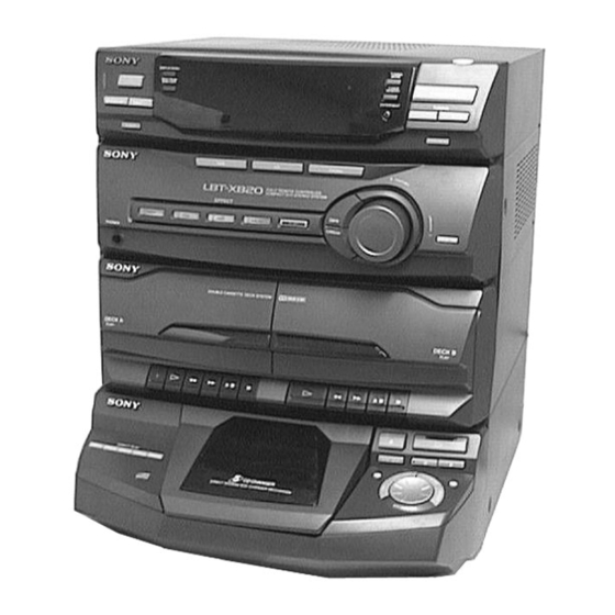
Photo : HCD-XB20
Model Name Using Similar Mechanism
CD Mechanism Type
CD
Base Unit Type
SECTION
Optical Pick-up Type
Model Name Using Similar Mechanism
TAPE
DECK
Tape Transpor
SECTION
Mechanism Type
SPECIFICATIONS
Peak music power output (Reference)
Inputs
PHONO IN (phone jacks):
Outputs
PHONES (stereo phone jack):
SPEAKER:
CD player section
System
Laser
Laser output
Frequency response
Wavelength
Tape deck section
Recording system
Frequency response
(DOLBY NR OFF)
MINI Hi-Fi COMPONENT SYSTEM
US Model
HCD-G2500
AEP Model
UK Model
HCD-XB20
E Model
Australian Model
HCD-XB22
NEW
CDM375BD29
KSM-213ECM
KSS-213B/SN
HCD-GRX2/RX33
DECK-A
TK20FX-SW943-800
DECK-B
TK20FX-SW943-800
800 W
sensitivity 3 mV, impedance 47 kilohms
accepts headphones of 8 Ω or more
accepts impedance of 6 to 16 Ω
Compact disc and degital audio system
Semiconductor laser ( λ = 780 nm)
Emission duration: continuous
Max.44.6 µW*
*This output is the value measured at a
distance of 200 mm from the objective
lens surface on the Optical Pick-up Block
with 7 mm aperture
20 Hz – 20 kHz (±0.5 dB)
780 – 790nm
4-track 2-channel stereo
60 – 13,000 Hz (±3 dB),
using a Sony TYPE I cassette
— Continued on next page —
Advertisement
Table of Contents

Related Manuals for Sony HCD-G2500


Summary of Contents for Sony HCD-G2500
- Page 1 DIN power output (Rated) 45 W + 45 W (6 Ω at 1 kHz, DIN) (DOLBY NR OFF) using a Sony TYPE I cassette Continuous RMS power output (Reference) 55 W + 55 W (6 Ω at 1 kHz, 10% THD) —...
- Page 2 COMPONENTS IDENTIFIED BY MARK ! OR DOTTED LINE WITH MARK ! ON THE SCHEMATIC DIAGRAMS AND IN THE PARTS LIST ARE CRITICAL TO SAFE OPERATION. REPLACE THESE COMPONENTS WITH SONY PARTS WHOSE PART NUMBERS APPEAR AS SHOWN IN THIS MANUAL OR IN SUPPLEMENTS PUBLISHED BY SONY.
-
Page 3: Table Of Contents
TABLE OF CONTENTS SAFETY CHECK-OUT 1. GENERAL ········································································· 4 After correcting the original service problem, perform the following —FRONT PANEL— ························································· 4 safety checks before releasing the set to the customer: —BACK PANEL— ···························································· 5 Check the antenna terminals, metal trim, “metallized” knobs, screws, 2. -
Page 4: General
SECTION 1 GENERAL – FRONT PANEL – $ª %º !º $• !™ !£ !¡ !¢ !∞ $£ $¢ $∞ $§ $¶ !§ $™ !¶ !ª @º !• @¡ @™ #§ #¶ #• #ª $º $¡ @¢ @£ #¡ #™ #£ #¢ #∞... -
Page 5: Back Panel
– BACK PANEL – ANTENNA terminal PHONO jack SPEAKER terminal — 5 —... -
Page 6: Disassembly
SECTION 2 DISASSEMBLY Note : Follow the disassembly procedure in the numerical order given. 2-1. TOP COVER 3 Top cover 1 Three screws 1 Three screws 2 Seven screws 2-2. FRONT PANEL ASSY 1 Screw 3 Front panel assy 2 Four screws —... -
Page 7: Main Board
2-3. MAIN BOARD 1 Three screws 3 Rear panel 5 Two flat wires 2 Two screws 7 MAIN board 1 Two screws 2 Three screws 6 Two screws 2 Three screws 4 Connector 2-4. MAIN SECTION 2 Main section 1 Two screws 1 Two screws —... -
Page 8: Cd Mechanism Deck Section
2-5. CD MECHANISM DECK SECTION 3 Five screws (BVTP 3 × 8) 4 CD mechanism deck section 2 Flat wire and lead wire 1 Open the clamp. 2-6. TAPE MECHANISM DECK 1 Six screws 2 Tape mechanism deck — 8 —... -
Page 9: Cassette Door
2-7. CASSETTE DOOR 3 Door spring 2 Cassette door (L) 3 Door spring 1 Cassette door (R) 2-8. CD DOOR ASSY 6 Four screws 7 Connector 8 CD door assy 4 Screw 5 DOOR SW board 1 Three screws 2 PLAY SW board 3 Three flat wires —... -
Page 10: Base Unit
2-9. BASE UNIT 3 Base unit 1 Yoke bracket 2 Boss 2-10. DISC TABLE Note: When the disc table is installed, adjust the positions of roller cam and mark z as shown in the figure, then set to the groove of disc table. 3 Step screw 1 Screw (BVTP 3 ×... -
Page 11: Mechanical Adjustments
SECTION 3 SECTION 4 MECHANICAL ADJUSTMENTS ELECTRICAL ADJUSTMENTS DECK SECTION 0 dB=0.775V Precaution 1. Clean the following parts with a denatured alcohol-moistened Demagnetize the record/playback head with a head swab: damagnetizer. record/playback head pinch rollers Do not use a magnetized screwdriver for the adjustments. erase head rubber belts After the adjustments, apply suitable locking compound to the... - Page 12 Turn the adjustment screw and check output peaks. If the peaks After the adjustments, apply suitable locking compound to the do not match for L-CH and R-CH, turn the adjustment screw parts adjusted. so that outputs match within 2 dB of peak. Adjustment Location: Remove the cassette lid before adjustment (See page 9) L-CH...
- Page 13 TUNER SECTION 0 dB=1µV AM Tuning Voltage Adjustment Main board DC voltmeter – Procedure: Set the reception frequency of the unit to 530 kHz. Adjust L105 for 1.2 ± 0.05 V reading on the DC voltmeter. Set the reception frequency of the unit to 1,710 kHz. Confirm that the voltage reading on the DC voltmeter is within 8.0 ±...
- Page 14 FM Tracking Adjustment FM Tuned Level Adjustment (US, Australian, Mexican model) FM RF SSG 75 Ω coaxial Procedure: FM RF SSG oscilloscope Carrier frequency : 98 MHz FM ANTENNA terminal Modulation : AUDIO 1 kHz, 75 kHz (JK101) deviation (100%) SPEAKER terminal (JK703) : 28 dB (at 75 Ω...
- Page 15 CD SECTION RF Level Check oscilloscope CD DECODER Note: board CD Block is basically constructed to operate without TP01 adjustment. Therefore, check each item in order given. Use YEDS-18 disc (3-702-101-01) unless otherwise indicated. Use an oscilloscope with more than 10MΩ impedance. Clean the object lens by an applicator with neutral detergent Procedure : when the signal level is low than specified value with the...
-
Page 16: Diagrams
SECTION 5 DIAGRAMS 5-1. CIRCUIT BOARDS LOCATION AMP board MAIN board POWER SELECT board POWER SUPPLY LED board board FRONT board DISC board VR board DOOR SW board PLAY SW board JOG board R/P SWITCH board DISC NO LED board TABLE SENSOR board MOTOR (6P)(C) board MOTOR board... -
Page 17: Block Diagram -Deck Section
HCD-G2500/XB20/XB22 5-2. BLOCK DIAGRAM — DECK SECTION — SELECTOR IC301 JK301 LINE AMP IC402 IC303 HP AMP IC401 PHONO R CH R CH Q301 JK401 Q407 PHONES ROCK PB/REC MUTE EQ AMP DOLBY IC801 Q803 IC802 Q404 IC803 IC803 Q303... -
Page 18: Block Diagram -Tuner/Cd Section
HCD-G2500/XB20/XB22 5-3. BLOCK DIAGRAM — TUNER/CD SECTION — FM/AM MPX FM FRONT END (FE101 model) IC102 L101 IC101 (FE101) FM ANT T101 Q101 CF101 CF102 TU L 10.7MHz 10.7MHz FM IF AM/FM RF IF MUTE DECODER 75Ω IF BUFF R CH... -
Page 19: Ic Block Diagrams
HCD-G2500/XB20/XB22 5-15. IC BLOCK DIAGRAMS 5-16. IC PIN FUNCTION DESCRIPTION IC601 LC866528A-5G83 (FRONT BOARD) IC101 (MAIN BOARD) LA1186 IC103 (MAIN BOARD) LC7218-ST IC03 (MAIN BOARD) BA5941FP IC01 (CD DECODER BOARD) CXA1782BQ Pin No. Pin Name Description Pin No. Pin Name... -
Page 20: Exploded Views
SECTION 6 EXPLODED VIEWS NOTE: • -XX, -X mean standardized parts, so they may • Hardware (# mark) list and accessories and The components identified by mark ! or have some differences from the original one. packing materials are given in the last of this dotted line with mark ! are critical for safety. -
Page 21: Cd Door Section
6-2. CD DOOR SECTION not supplied Ref. No. Part No. Description Remarks Ref. No. Part No. Description Remarks * 51 1-670-947-11 JOG BOARD 4-211-526-01 DOOR, CD (G2500) 4-211-523-01 BUTTON, EDIT (G2500) 4-211-573-01 DOOR, CD (XB22,XB20) 4-211-570-01 BUTTON, EDIT (XB22,XB20) 4-211-917-01 SPRING, CD EJECT 4-211-522-01 PANEL, AMS (G2500) * 61 4-211-921-01 CHASSIS, CD DOOR... -
Page 22: Panel Section
6-3. PANEL SECTION supplied 116 117 Ref. No. Part No. Description Remarks Ref. No. Part No. Description Remarks 4-211-480-01 KNOB, VOLUME (G2500) 4-211-508-01 HOLDER, ROCK BUTTON 4-211-557-01 KNOB, VOLUME (XB22,XB20) 4-211-498-01 KNOB, ROCK 4-211-475-01 DOOR (R), CASSETTE (G2500) 4-211-499-01 KNOB, POP 4-211-554-01 DOOR (R), CASSETTE (XB22,XB20) 4-211-501-01 KNOB, JAZZ 4-211-477-01 WINDOW (R), CASSETTE... -
Page 23: Main Section
6-4. MAIN SECTION E, MX not supplied not supplied not supplied SP, MY, AR, AEP, UK not supplied PT301 not supplied Ref. No. Part No. Description Remarks Ref. No. Part No. Description Remarks * 151 A-4414-973-A MAIN BOARD, COMPLETE(XB22:MX,G2500) ! 157 1-555-795-00 CORD, POWER, EULO PLUG (SP,MY,AR,AEP) * 151 A-4414-978-A MAIN BOARD, COMPLETE(XB20) -
Page 24: Cassette Button Section
6-5. CASSETTE BUTTON SECTION Ref. No. Part No. Description Remarks Ref. No. Part No. Description Remarks 4-211-511-01 BUTTON, REC 4-211-517-01 BUTTON (B), PLAY 4-211-512-01 BUTTON (A), PLAY 4-211-518-01 BUTTON (B), REW 4-211-513-01 BUTTON (A), REW 4-211-519-01 BUTTON (B), FF 4-211-514-01 BUTTON (A), FF 4-211-520-01 BUTTON (B), STOP 4-211-515-01 BUTTON (A), STOP 4-211-521-01 BUTTON (B), PAUSE... -
Page 25: Cassette Mechanism Deck Section
6-6. CASSETTE MECHANISM DECK SECTION (TCK20FX-SW943-800) not supplied not supplied M901 SW202 not supplied HE901 SW203 HRP901 supplied SW204 not supplied not supplied HP901 not supplied not supplied not supplied Ref. No. Part No. Description Remarks Ref. No. Part No. Description Remarks 9-980-286-01 CAP SCREW 2 ×... -
Page 26: Cd Mechanism Deck Section
6-7. CD MECHANISM DECK SECTION not supplied not supplied not supplied supplied Base unit block Ref. No. Part No. Description Remarks Ref. No. Part No. Description Remarks 4-987-976-01 SCREW, STEP * 360 X-4924-457-1 ROLLER ASSY 4-944-490-01 BELT (TIMING) * 361 4-978-583-01 BRACKET (BU) 4-978-421-01 GEAR (MID) * 364... -
Page 27: Base Unit Section
6-8. BASE UNIT SECTION (KSM-213ECM) not supplied not supplied M102 M101 Ref. No. Part No. Description Remarks Ref. No. Part No. Description Remarks 4-992-164-01 BASE, KSM MECHANICAL ! 408 8-848-379-31 OPTICAL PICK-UP KSS-213B/SN 4-992-165-01 DAMPER (GREEN) * 409 1-639-678-12 MOTOR (6P) (C) BOARD 4-992-166-01 DAMPER (RED) 1-783-740-11 WIRE (FLAT TYPE)(16 CORE) 4-985-672-21 SCREW (+PTPWHM2.6), FLOATING... -
Page 28: Electrical Parts List
SECTION 7 ELECTRICAL PARTS LIST NOTE: • Due to standardization, replacements in the • RESISTORS When indicating parts by reference number, parts list may be different from the parts All resistors are in ohms. please include the board name. specified in the diagrams or the components METAL: metal-film resistor used on the set. - Page 29 CD DECODER Ref. No. Part No. Description Remarks Ref. No. Part No. Description Remarks < TRANSISTOR > < RELAY > Q701 8-729-188-23 TRANSISTOR 2SD882-P RL701 1-515-921-11 RELAY (12V) Q702 8-729-188-23 TRANSISTOR 2SD882-P ************************************************************ Q703 8-729-232-32 TRANSISTOR 2SA965 Q706 8-729-140-82 TRANSISTOR 2SA988-PAFAEA A-4414-990-A CD DECODER BOARD, COMPLETE Q707 8-729-184-53 TRANSISTOR 2SC1845-EA...
- Page 30 CD DECODER Ref. No. Part No. Description Remarks Ref. No. Part No. Description Remarks 1-136-154-00 FILM 0.012uF < RESISTOR > 1-162-284-31 CERAMIC 150PF 1-162-284-31 CERAMIC 150PF 1-249-393-11 CARBON 1/4W F 1-162-288-31 CERAMIC 330PF 1-247-847-11 CARBON 4.7K 1/4W 1-162-288-31 CERAMIC 330PF 1-247-863-11 CARBON 1/4W 1-249-430-11 CARBON...
- Page 31 CD DECODER CONNECTOR DISC DISC NO LED DOOR SW FRONT Ref. No. Part No. Description Remarks Ref. No. Part No. Description Remarks 1-249-442-11 CARBON 1/4W < SWITCH > 1-247-855-11 CARBON 1/4W 1-247-855-11 CARBON 1/4W S636 1-771-478-11 SWITCH (DISC 1) 1-247-855-11 CARBON 1/4W S637 1-771-478-11 SWITCH (DISC 2)
- Page 32 FRONT Ref. No. Part No. Description Remarks Ref. No. Part No. Description Remarks C628 1-126-964-11 ELECT 10uF < IC > C629 1-126-960-11 ELECT C630 1-162-294-31 CERAMIC 0.001uF IC601 8-759-545-53 IC LC866528A-5G83 C631 1-136-156-00 FILM 0.018uF IC602 8-759-275-23 IC BU2092 C632 1-136-156-00 FILM 0.018uF IC603...
- Page 33 FRONT Ref. No. Part No. Description Remarks Ref. No. Part No. Description Remarks R651 1-247-807-11 CARBON 1/4W S606 1-771-478-11 SWITCH, TACTILE (SPEANA) R652 1-247-807-11 CARBON 1/4W S607 1-771-478-11 SWITCH, TACTILE (TUNING MODE) R653 1-247-871-11 CARBON 1/4W S608 1-771-478-11 SWITCH, TACTILE (TUNING MEMORY) R654 1-247-855-11 CARBON 1/4W...
- Page 34 MAIN Ref. No. Part No. Description Remarks Ref. No. Part No. Description Remarks A-4414-973-A MAIN BOARD, COMPLETE (XB22:MX,G2500) C135 1-162-285-31 CERAMIC 180PF (XB22:E,SP,MY,AR,XB20) ************************************ A-4414-978-A MAIN BOARD, COMPLETE (XB20) C137 1-126-959-11 ELECT 0.47uF C138 1-162-306-11 CERAMIC 0.01uF *************************** A-4414-982-A MAIN BOARD, COMPLETE (XB22:E,SP,MY,AR) C139 1-161-494-00 CERAMIC 0.022uF...
- Page 35 MAIN Ref. No. Part No. Description Remarks Ref. No. Part No. Description Remarks C190 1-164-159-11 CERAMIC 0.1uF C354 1-126-960-11 ELECT C192 1-161-494-00 CERAMIC 0.022uF C355 1-126-933-11 ELECT 100uF C193 1-162-294-31 CERAMIC 0.001uF C356 1-126-933-11 ELECT 100uF (XB22:E,SP,MY,AR,XB20) C368 1-109-889-11 ELECT C194 1-162-294-31 CERAMIC 0.001uF...
- Page 36 MAIN Ref. No. Part No. Description Remarks Ref. No. Part No. Description Remarks C444 1-162-302-11 CERAMIC 0.0022uF 30% C854 1-130-474-00 MYLAR 0.0018uF 5% C445 1-162-302-11 CERAMIC 0.0022uF 30% C855 1-126-964-11 ELECT 10uF C446 1-126-962-11 ELECT 3.3uF C856 1-126-964-11 ELECT 10uF C447 1-126-962-11 ELECT 3.3uF...
- Page 37 MAIN Ref. No. Part No. Description Remarks Ref. No. Part No. Description Remarks < DIODE > L106 1-412-507-11 INDUCTOR 47uH L107 1-416-741-11 COIL (LW ANT) (XB22:E,SP,MY,AR,XB20) D101 8-719-991-33 DIODE 1SS133T-77 L108 1-412-503-11 INDUCTOR 22uH (XB22:E,SP,MY,AR,XB20) D102 8-719-991-33 DIODE 1SS133T-77 L109 1-410-527-11 INDUCTOR 100uH (XB22:E,SP,MY,AR,XB20) D103 8-719-991-33 DIODE 1SS133T-77...
- Page 38 MAIN Ref. No. Part No. Description Remarks Ref. No. Part No. Description Remarks Q411 8-729-194-57 TRANSISTOR 2SC945-P R127 1-249-417-11 CARBON 1/4W F Q801 8-729-194-57 TRANSISTOR 2SC945-P R128 1-249-431-11 CARBON 1/4W Q802 8-729-194-57 TRANSISTOR 2SC945-P R129 1-249-431-11 CARBON 1/4W Q803 8-729-194-57 TRANSISTOR 2SC945-P R130 1-259-531-11 CARBON 1/2W...
- Page 39 MAIN Ref. No. Part No. Description Remarks Ref. No. Part No. Description Remarks R318 1-247-887-00 CARBON 220K 1/4W R390 1-249-465-11 CARBON 1/4W R319 1-247-855-11 CARBON 1/4W R391 1-247-871-11 CARBON 1/4W R320 1-247-855-11 CARBON 1/4W R393 1-249-431-11 CARBON 1/4W R321 1-249-434-11 CARBON 1/4W R394 1-249-544-11 CARBON...
- Page 40 MAIN Ref. No. Part No. Description Remarks Ref. No. Part No. Description Remarks R807 1-249-434-11 CARBON 1/4W R867 1-247-879-11 CARBON 100K 1/4W R808 1-249-417-11 CARBON 1/4W F R868 1-249-431-11 CARBON 1/4W R809 1-247-855-11 CARBON 1/4W R869 1-249-431-11 CARBON 1/4W R810 1-247-843-11 CARBON 3.3K 1/4W...
-
Page 41: Power Supply
MAIN MOTOR MOTOR (6P) (C) PLAY SW POWER SELECT POWER SUPPLY R/P SWITCH TABLE SENSOR Ref. No. Part No. Description Remarks Ref. No. Part No. Description Remarks < TRANSFORMER > < SWITCH > T101 1-429-553-11 TRANSFORMER, FM IFT (XB22:AUS,MX,G2500) S626 1-771-478-11 SWITCH (PLAY) T102 1-429-554-11 TRANSFORMER, AM IFT... - Page 42 SENSOR Ref. No. Part No. Description Remarks Ref. No. Part No. Description Remarks 1-670-944-11 SENSOR BOARD ACCESSORIES & PACKING MATERIALS ************ ******************************* < SENSOR > 1-475-829-11 REMOTE COMMANDER (RM-SG5) 1-501-374-11 ANTENNA, LOOP RM601 8-749-013-84 IC SPS-447-1 1-501-594-11 ANTENNA (FM) (XB22,G2500) 1-501-807-11 ANTENNA (FM) (XB20) ************************************************************ 3-862-441-11 MANUAL, INSTRUCTION (ENGLISH)
- Page 43 HCD-G2500/XB20/XB22 Sony Corporation 98E1686-1 Printed in Japan ©1998.5 Home A&V Products Company 9-922-866-11 Published by Quality Assurance Dept. — 96 — (Shibaura)
Need help?
Do you have a question about the HCD-G2500 and is the answer not in the manual?
Questions and answers