Table of Contents
Advertisement
HCD-GTR6/GTR6B/GTR7/GTR8/GTR8B
SERVICE MANUAL
Ver. 1.0 2009. 05
• HCD-GTR6/GTR7/GTR8
are the tuner, CD and
amplifi er section in
MHC-GTR6/GTR7/GTR8
• HCD-GTR6B/GTR8B
are the tuner, deck, CD and
amplifi er section in
MHC-GTR6/GTR7/GTR8
AUDIO POWER SPECIFICATION
Amplifi er section
MHC-GTR8 (HCD-GTR8/HCD-GTR8B)
The following are measured at
Mexican model:
AC 127 V, 60 Hz
Other models:
AC 120, 220, 240 V, 50/60 Hz
Front/Surround speaker
210 W + 210 W (at 6 Ω, 1 kHz, 1% THD,
Power Output (rated):
at LINK MODE)
Front speaker
RMS output power (reference):
280 W + 280 W (per channel at 8 Ω,
1 kHz, 10% THD)
Surround speaker
RMS output power (reference):
110 W + 110 W (per channel at 24 Ω,
1 kHz, 10% THD)
Subwoofer
RMS output power (reference):
160 W + 160 W (per channel at 6 Ω,
100 Hz, 10% THD)
9-890-515-01
Sony Corporation
2009E08-1
Audio & Video Business Group
© 2009. 05
Published by Sony EMCS (Malaysia) PG Tec
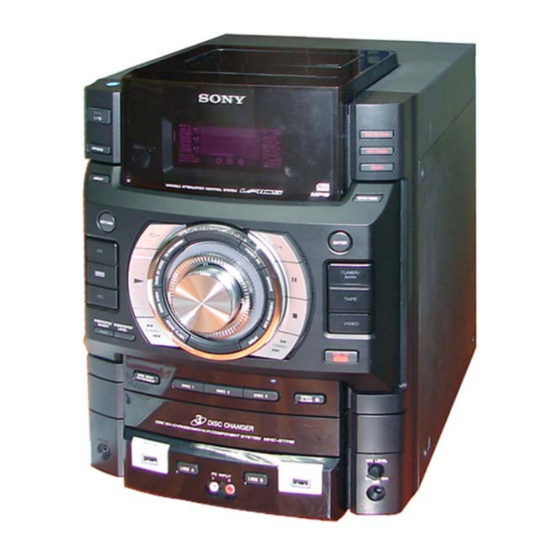
Photo : HCD-GTR8B (E Model)
CD
Section
Tape Deck Section
only for HCD-GTR6B/GTR8B
SPECIFICATIONS
HCD-GTR6/GTR6B/GTR7/GTR8/GTR8B
HCD-GTR6/GTR6B/GTR7/GTR8/GTR8B
Model Name Using Similar Mechanism
CD Mechanism Type
Optical Pick-up Name
Model Name Using Similar Mechanism
Tape Mechanism Type
MHC-GTR7 (HCD-GTR7)
The following are measured at
Mexican model:
AC 127 V, 60 Hz
Other models:
AC 120, 220, 240 V, 50/60 Hz
Front/Surround speaker
215 W + 215 W (at 6 Ω, 1 kHz, 1% THD, at LINK MODE)
Power Output (rated):
Front speaker
RMS output power (reference):
285 W + 285 W (per channel at 8 Ω, 1 kHz, 10% THD)
Surround speaker
RMS output power (reference):
Subwoofer
RMS output power (reference):
COMPACT DISC DECK RECEIVER
E Model
Australian Model
HCD-GTR6B/GTR8B
NEW
CDM74HF-DVBU101//M
KHM-313CAB/C2NP
HCD-GTX777/GTX787/GTX888
CFP42608
110 W + 110 W (per channel at 24 Ω,
1 kHz, 10% THD)
210 W (at 8 Ω, 100 Hz, 10% THD)
– Continued on next page –
1
Advertisement
Table of Contents

Related Manuals for Sony HCD-GTR7


Summarization of Contents
SPECIFICATIONS
AUDIO POWER SPECIFICATION
Details on audio output power for different MHC models.
General Specifications
Power Requirements and Dimensions
Specifies power voltage, frequency, and physical dimensions.
Repair and Handling Notes
Laser Diode Safety
Safety information for checking laser diode emission.
MODEL IDENTIFICATION
Model Number Label and Abbreviations
Explains model identification labels and abbreviations.
SECTION 1 DISASSEMBLY
1-1. CASE (TOP)
Procedure for removing the top case assembly.
1-16. Optical Pick-up
Procedure for removing the optical pick-up assembly.
SECTION 2 TEST MODE
[GC TEST MODE]
Checks fluorescent indicator tube, LEDs, keys, and model/software info.
[MC TEST MODE]
Checks operations of amplifier and tape sections.
[COLD RESET]
Clears RAM data to initial conditions, resets the set.
SECTION 3 MECHANICAL ADJUSTMENTS
Torque Measurement
Table detailing torque measurements for tape mechanism adjustments.
SECTION 4 ELECTRICAL ADJUSTMENTS
TUNER SECTION
Procedures for tuning adjustments.
DECK SECTION
Procedures for deck adjustments.
SECTION 5 DIAGRAMS
5-1. BLOCK DIAGRAM — USB SECTION —
Block diagram illustrating the USB section connectivity.
5-2. BLOCK DIAGRAM — RF/SERVO SECTION —
Block diagram of the RF and servo control systems.
5-3. BLOCK DIAGRAM — TAPE/TUNER SECTION —
Block diagram of the tape mechanism and tuner sections.
Waveforms
DMB19 BOARD — (CD PLAY)
Waveform examples for CD playback on the DMB19 board.
SECTION 5 DIAGRAMS
5-8. PRINTED WIRING BOARD — DISPLAY BOARD —
Printed wiring diagram for the display board.
5-9. SCHEMATIC DIAGRAM — DISPLAY BOARD —
Schematic diagram for the display board.
5-10. PRINTED WIRING BOARDS — DMB19 BOARD —
Printed wiring diagrams for the DMB19 board (Side A and Side B).
SECTION 5 DIAGRAMS
5-11. SCHEMATIC DIAGRAM — DMB19 BOARD (1/4) —
Schematic diagram part 1 of 4 for the DMB19 board.
5-12. SCHEMATIC DIAGRAM — DMB19 BOARD (2/4) —
Schematic diagram part 2 of 4 for the DMB19 board.
5-13. SCHEMATIC DIAGRAM — DMB19 BOARD (3/4) —
Schematic diagram part 3 of 4 for the DMB19 board.
SECTION 5 DIAGRAMS
5-14. SCHEMATIC DIAGRAM — DMB19 BOARD (4/4) —
Schematic diagram part 4 of 4 for the DMB19 board.
5-15. PRINTED WIRING BOARD — FRONT BOARD —
Printed wiring diagram for the front board.
5-16. SCHEMATIC DIAGRAM — FRONT BOARD —
Schematic diagram for the front board.
SECTION 5 DIAGRAMS
5-17. PRINTED WIRING BOARD — MAIN BOARD —
Printed wiring diagram for the main board.
5-18. SCHEMATIC DIAGRAM — MAIN BOARD (1/5) —
Schematic diagram part 1 of 5 for the main board.
5-19. SCHEMATIC DIAGRAM — MAIN BOARD (2/5) —
Schematic diagram part 2 of 5 for the main board.
SECTION 5 DIAGRAMS
5-20. SCHEMATIC DIAGRAM — MAIN BOARD (3/5) —
Schematic diagram part 3 of 5 for the main board.
5-21. SCHEMATIC DIAGRAM — MAIN BOARD (4/5) —
Schematic diagram part 4 of 5 for the main board.
5-22. SCHEMATIC DIAGRAM — MAIN BOARD (5/5) —
Schematic diagram part 5 of 5 for the main board.
SECTION 5 DIAGRAMS
5-23. PRINTED WIRING BOARD — MIC CD AND MIC RV BOARD —
Printed wiring diagrams for MIC CD and MIC RV boards.
5-24. SCHEMATIC DIAGRAM — MIC CD AND MIC RV BOARD —
Schematic diagrams for MIC CD and MIC RV boards.
SECTION 5 DIAGRAMS
5-25. PRINTED WIRING BOARD — STR AND CD_SW BOARD —
Printed wiring diagrams for STR and CD_SW boards.
5-26. SCHEMATIC DIAGRAM — STR AND CD_SW BOARD —
Schematic diagrams for STR and CD_SW boards.
SECTION 5 DIAGRAMS
5-27. PRINTED WIRING BOARD — TRANS AND SUB TRANS BOARD —
Printed wiring diagrams for the TRANS and SUB TRANS boards.
5-28. SCHEMATIC DIAGRAM — TRANS AND SUB TRANS BOARD —
Schematic diagrams for the TRANS and SUB TRANS boards.
SECTION 5 DIAGRAMS
5-29. PRINTED WIRING BOARD — SUBWOOFER BOARD —
Printed wiring diagram for the subwoofer board.
5-30. SCHEMATIC DIAGRAM — SUBWOOFER BOARD —
Schematic diagram for the subwoofer board.
SECTION 5 DIAGRAMS
5-31. PRINTED WIRING BOARDS — HEADPHONE AND USB CD BOARD —
Printed wiring diagrams for HEADPHONE and USB CD boards.
5-32. SCHEMATIC DIAGRAM — HEADPHONE AND USB CD BOARD —
Schematic diagrams for HEADPHONE and USB CD boards.
SECTION 5 DIAGRAMS
5-33. PRINTED WIRING BOARDS — HUB BOARD —
Printed wiring diagrams for the HUB board (Side A and Side B).
5-34. SCHEMATIC DIAGRAM — HUB BOARD —
Schematic diagram for the HUB board.
SECTION 5 DIAGRAMS
5-35. PRINTED WIRING BOARDS — DRIVE BOARD —
Printed wiring diagrams for MOTOR (LD), DRIVER (F), SENSOR, and SW boards.
5-36. SCHEMATIC DIAGRAM — DRIVE BOARD —
Schematic diagrams for MOTOR (LD), DRIVER (F), SENSOR, and SW boards.
IC Block Diagrams
IC107 TK11133CSCL-G (DMB19 Board)
Internal block diagram of the IC107 TK11133CSCL-G chip.
IC201 FAN8036L (DMB19 Board)
Internal block diagram of the IC201 FAN8036L chip.
IC Block Diagrams
IC4601 PCM1808PWR (DMB19 Board)
Internal block diagram of the IC4601 PCM1808PWR chip.
IC4602 CS4335-KSZR (DMB19 Board)
Internal block diagram of the IC4602 CS4335-KSZR chip.
IC Block Diagrams
IC1500 NJM2903V (TE2) (HUB Board)
Internal block diagram of the IC1500 NJM2903V chip.
IC Block Diagrams
IC400 R2A15216FP (MAIN Board)
Internal block diagram of the IC400 R2A15216FP chip.
IC675 BR24S16FJ-WE2 (MAIN Board)
Internal block diagram of the IC675 BR24S16FJ-WE2 chip.
IC Block Diagrams
IC800 STK433-130-E (SUB WOOFER Board)
Internal block diagram of the IC800 STK433-130-E chip.
IC701 BA6956AN (DRIVE Board)
Internal block diagram of the IC701 BA6956AN chip.
SECTION 6 EXPLODED VIEWS
6-1. MAIN SECTION
Exploded view and parts list for the main section assembly.
6-2. BACK PANEL SECTION
Exploded view and parts list for the back panel section.
6-3. FRONT PANEL SECTION (1)
Exploded view and parts list for the front panel section (part 1).
SECTION 6 EXPLODED VIEWS
6-4. FRONT PANEL SECTION (2)
Exploded view and parts list for the front panel section (part 2).
6-5. CHASSIS SECTION
Exploded view and parts list for the chassis assembly.
6-6. CD MECHANISM SECTION (1) (CDM74KF-K6BD93UR-WOD)
Exploded view and parts list for CD mechanism section (part 1).
SECTION 6 EXPLODED VIEWS
6-7. CD MECHANISM SECTION (2) (CDM74KF-K6BD93UR-WOD)
Exploded view and parts list for CD mechanism section (part 2).
SECTION 7 ELECTRICAL PARTS LIST
CD SW BOARD Components
Electrical components list for the CD SW board.
DISPLAY BOARD Components
Electrical components list for the Display board.
REVISION HISTORY
Version 1.0 (2009.05)
Initial release of the service manual.
Need help?
Do you have a question about the HCD-GTR7 and is the answer not in the manual?
Questions and answers