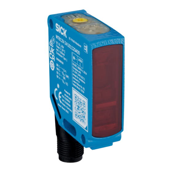
Summarization of Contents
1 About this document
1.1 Further information
Provides information on finding product details, data sheets, and other documentation online.
1.2 Symbols and document conventions
Explains the meaning of warning symbols, notes, and instruction formats used in the manual.
2 Safety information
2.1 General safety notes
Covers general safety precautions for installation, operation, and environmental exposure.
Laser notes
Details safety precautions regarding laser radiation, classification, and eye safety.
2.2 Intended use
Specifies the product's intended application and the consequences of misuse.
3 Product description
3.1 Operating elements and status indicators
Identifies and explains the function of the sensor's buttons, LEDs, and display elements.
4 Mounting
Mounting with the background suppression principle of operation
Guides on aligning the sensor for optimal performance with background suppression.
5 Electrical installation
5.1 Notes on electrical installation
Provides essential instructions and warnings for safe and correct electrical hook-up.
Layout of data cables
Offers guidance on proper data cable routing and shielding for EMC compliance.
Notes on UL approval
Outlines specific requirements and conditions for achieving UL approval.
5.3 Connection notes
Details connection procedures for standard I/O and IO-Link modes, including pin assignments.
6 Commissioning
6.1 Alignment
Instructs on the correct physical alignment of the sensor with the target object.
Alignment with background suppression
Provides specific alignment instructions for the WTB12V model using laser positioning.
6.2 Check the application conditions
Explains how to verify and adjust sensing range based on object remission and background.
6.3 Setting
Sensing range adjustment
Describes methods for adjusting the sensor's sensing range using its controls.
Teach-Turn adjustment
Details the procedure for adjusting the sensing range using the teach-turn functionality.
6.4 Additional functions
IO-Link
Explains the use of the sensor in IO-Link mode for advanced functionality.
9 Maintenance
Cleaning
Provides instructions and precautions for cleaning the sensor's optical surfaces and housing.
10 Technical data
10.1 Technical specifications
Lists key performance parameters, ranges, and optical characteristics of the sensor.
Communication interface
Details the sensor's communication capabilities, focusing on IO-Link protocols.
Electrical data
Specifies the electrical requirements, including supply voltage, ripple, and current consumption.
10.2 Dimensional drawings
Presents detailed physical dimensions and mounting hole information for the sensor.
Digital output
Describes the characteristics of the sensor's digital output, such as response time and frequency.
Mechanical data
Covers physical attributes like enclosure rating and operating temperature range.
11 Annex
11.1 Conformities and certificates
Guides users on how to obtain product compliance declarations and certificates from the manufacturer's website.


Need help?
Do you have a question about the WTB12L 8 Series and is the answer not in the manual?
Questions and answers