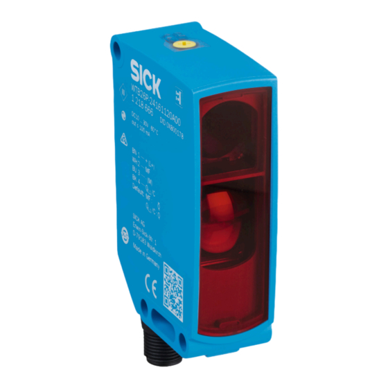
SICK WTB26 Operating Instructions Manual
Hide thumbs
Also See for WTB26:
- Operating instructions manual (168 pages) ,
- Operating instructions manual (288 pages)
Table of Contents
Advertisement
Advertisement
Table of Contents

Summary of Contents for SICK WTB26
- Page 1 O P E R A T I N G I N S T R U C T I O N S WTB26...
- Page 2 O P E R A T I N G I N S T R U C T I O N S WTB26...
- Page 3 This work is protected by copyright. Any rights derived from the copyright shall be reserved for SICK AG. Reproduction of this document or parts of this document is only permissible within the limits of the legal determination of Copyright Law. Any modifica‐...
-
Page 4: Table Of Contents
Technical data..................16 12.1 Dimensional drawings................Safety information................General safety notes................Notes on UL approval................Intended use..................Operating and status indicators............Mounting..................... Electrical installation................ Additional functions................Commissioning.................. Process data structure..............14 Troubleshooting................. 14 8020354.14CS | SICK Subject to change without notice... - Page 5 Disassembly and disposal............... 15 Maintenance..................15 Technical data..................16 12.1 Dimensional drawings................8020354.14CS | SICK Subject to change without notice...
-
Page 6: Safety Information
UL Environmental Rating: Enclosure type 1 Intended use The WTB26 is an opto-electronic photoelectric proximity sensor (referred to as “sensor” in the following) for the optical, non-contact detection of objects, animals, and persons. If the product is used for any other purpose or modified in any way, any warranty claim against SICK AG shall become void. -
Page 7: Mounting
Press-turn element: time function adjustment Teach pushbutton: adjustment of light/dark switching Mounting Mount the sensor using a suitable mounting bracket (see the SICK range of acces‐ sories). Note the sensor’s maximum permissible tightening torque of < 1,3 Nm. Note the preferred direction of the object relative to the... - Page 8 1 = BN 2 = WH 2 = WH 3 = BU 3 = BU 4 = BK 4 = BK 0.14 mm 0.14 mm AWG26 AWG26 Table 3: Push / pull 8020354.14CS | SICK Subject to change without notice...
-
Page 9: Additional Functions
HIGH (1), if excessively contaminated or in the event of cable interrup‐ tion LOW (0). The LED indicator flashes in this case. Test input Test input: The WTB26 sensors feature a test input (“TI” or “Test” on the connection diagram [see table... -
Page 10: Commissioning
Commissioning Alignment WTB26 P: Align sensor on object. Select the position so that the red emitted light beam hits the center of the object. It is important to ensure that the optical opening (front screen) of the sensor is completely clear... - Page 11 2,400 3,200 (31.5) (62.99) (94.49) (125.98) Distance in mm (inch) Figure 4: Characteristic line 2, WTB26 P-xxxxx4 xx, red light Minimum distance in mm (y) between the set sensing 100 / 1,000 range and background (white, 90%) white background (90%)
- Page 12 (see table table table 1...3 sec. Figure 7: WTB26 x-xxxxxx2 xAxx, adjusting the sensing range with press-turn element 8020354.14CS | SICK Subject to change without notice...
- Page 13 (see table table table Figure 8: WTB26 x-xxxxxx1 xAxx, adjusting the sensing range with potentiometer 8020354.14CS | SICK Subject to change without notice...
- Page 14 (see table table table 1...3 sec. Figure 9: WTB26 x-xxxxxx3 xAxx, adjusting the sensing range with teach-in button Time function setting Input signal M = Manual (specific setting via IO-Link) 1 ms 30.000 ms...
-
Page 15: Process Data Structure
/ Data surement type value] / UInt13 Troubleshooting The Troubleshooting table indicates measures to be taken if the sensor stops working. LED indicator/fault pattern Cause Measures Green LED flashes IO-Link communication None 8020354.14CS | SICK Subject to change without notice... -
Page 16: Disassembly And Disposal
• This symbol on the product, its package or in this document, indicates that a product is subject to these regulations. Maintenance SICK sensors are maintenance-free. We recommend doing the following regularly: • Clean the external lens surfaces •... -
Page 17: Technical Data
Replaces IP69 K pursuant to ISO 20653: 2013-03 A = U -connections reverse polarity protected B = inputs and output reverse-polarity protected C = Interference suppression D = outputs overcurrent and short-circuit protected Do not bend cables below 0°C. 8020354.14CS | SICK Subject to change without notice... -
Page 18: Dimensional Drawings
Center of optical axis, receiver Fixing hole, Ø5.2 mm Connection LED indicator green: Supply voltage active LED indicator yellow: Status of received light beam Press-turn element: Adjusting the sensing range BluePilot blue: Sensing range dis‐ play 8020354.14CS | SICK Subject to change without notice...


Need help?
Do you have a question about the WTB26 and is the answer not in the manual?
Questions and answers