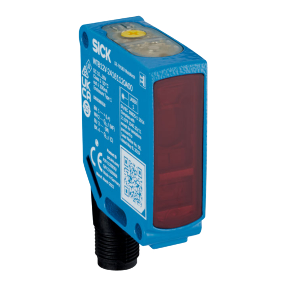
Summarization of Contents
1 About this document
1.1 Further information
Details on accessing product pages, data sheets, CAD files, certificates, software, and accessories.
1.2 Symbols and document conventions
Explanation of warning symbols (DANGER, WARNING, CAUTION, NOTICE, NOTE) and instruction formatting.
2 Safety information
2.1 General safety notes
General safety guidelines for connection, mounting, and operation, including UV radiation and moisture protection.
Laser notes
Cautionary notes on laser radiation hazards, focusing, and compliance with safety standards.
2.2 Intended use
Defines the product's purpose as a proximity sensor and notes warranty voidance for other uses.
3 Product description
3.1 Operating elements and status indicators
Description of the sensor's operating elements, status indicators like BluePilot and LEDs.
4 Mounting
Mounting with the background suppression principle of operation
Guidance on mounting with background suppression, including alignment relative to object direction.
5 Electrical installation
5.1 Notes on electrical installation
Important notes on electrical installation, supply voltage, working with live parts, and safety requirements.
Layout of data cables
Guidelines for data cable layout, shielding, EMC considerations, and IP enclosure rating.
5.2 Notes on UL approval
Information on UL approval requirements for the device's power supply and secondary protective device.
6 Commissioning
6.1 Alignment
Instructions for aligning the sensor with the object for optimal performance, including visual checks.
Alignment with background suppression
Specific alignment for background suppression, ensuring the optical opening is clear.
6.3 Setting
Sensing range adjustment
Instructions for adjusting the sensing range using the teach-in button or potentiometer.
6.4 Additional functions
IO-Link
Explanation of using the sensor in standard I/O or IO-Link mode, and output signal configuration.
9 Maintenance
Cleaning
Instructions for cleaning optical surfaces and housing using specific cleaning agents and tools.
10 Technical data
Features
Overview of sensor features, including sensing range and emitted beam characteristics.
Key laser figures
Key laser figures for the WTB12L/WTB12V series, including laser class and wavelength.
Communication interface
Details on the communication interface, specifically IO-Link, including data transmission rate.
Electrical data
Specifications for supply voltage, ripple, current consumption, and protection class.
10.4 Process data structure
IO-Link
Structure of IO-Link process data, defining bytes and data types for communication.
11 Annex
11.1 Conformities and certificates
Information on obtaining product conformity declarations, certificates, and operating instructions from the manufacturer's website.


Need help?
Do you have a question about the WTB12L 2 Series and is the answer not in the manual?
Questions and answers