Table of Contents
Advertisement
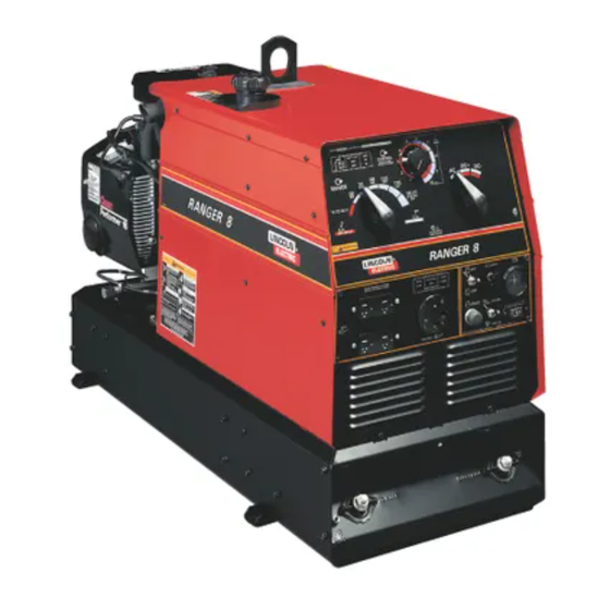
RANGER 10,000 /10,000 PLUS
Safety Depends on You
Lincoln arc welding and cutting
equipment is designed and built
with safety in mind. However,
your overall safety can be
increased by proper installation
. . . and thoughtful operation on
your part. DO NOT INSTALL,
OPERATE OR REPAIR THIS
EQUIPMENT WITHOUT READ-
ING THIS MANUAL AND THE
SAFETY PRECAUTIONS CON-
TAINED THROUGHOUT. And,
most importantly, think before
you act and be careful.
Cleveland, Ohio 44117-1199 U.S.A. TEL: 216.481.8100 FAX: 216.486.1751 WEB SITE: www.lincolnelectric.com
All manuals and user guides at all-guides.com
®
For use with machine code numbers: Kohler 11041, 11151, 11394
SERVICE MANUAL
• World's Leader in Welding and Cutting Products •
• Sales and Service through Subsidiaries and Distributors Worldwide •
SVM168-B
Honda 11095, 11398
Robin/Subaru 11253. 11395
Copyright © Lincoln Global Inc.
April, 2010
Advertisement
Chapters
Table of Contents
Troubleshooting

Related Manuals for Lincoln Electric K1419-4


Summarization of Contents
SAFETY
CALIFORNIA PROPOSITION 65 WARNINGS
Warnings regarding diesel and engine exhaust constituents known to cause cancer and birth defects.
FOR ENGINE powered equipment.
Safety precautions specific to engine-powered equipment operation and maintenance.
ELECTRIC AND MAGNETIC FIELDS may be dangerous
Information on potential health effects of EMF fields and precautions for welders.
SAFETY
ELECTRIC SHOCK can kill.
Precautions to prevent electrocution, including insulation and dry gloves.
ARC RAYS can burn.
Guidelines for protecting eyes and skin from arc rays and spatter.
FUMES AND GASES can be dangerous.
Safety measures for avoiding hazardous fumes and gases during welding operations.
SAFETY
CYLINDER may explode if damaged.
Safety precautions for handling compressed gas cylinders to prevent explosion.
WELDING and CUTTING SPARKS can cause fire or explosion.
Measures to prevent fires and explosions caused by welding sparks and hot materials.
FOR ELECTRICALLY powered equipment.
Safety requirements for electrical installation and grounding of equipment.
INSTALLATION
TECHNICAL SPECIFICATIONS - RANGER® 10,000 (K1419-4 ), (K2160-3 ) and (K2468-1)
Detailed technical specifications for the RANGER 10,000 models including engine and output ratings.
INSTALLATION
TECHNICAL SPECIFICATIONS - RANGER 10,000 PLUS (K1419-5 ), (K2468-2)
Detailed technical specifications for the RANGER 10,000 PLUS models including engine and output ratings.
INSTALLATION
SAFETY PRECAUTIONS
General safety warnings for operating the welder, including electric shock and engine exhaust hazards.
MACHINE GROUNDING
Instructions on proper grounding procedures for the portable welder and connected equipment.
SPARK ARRESTER
Information on the requirement and installation of spark arresters for gasoline engines.
TOWING
Recommendations and factors to consider when towing the welding equipment.
INSTALLATION
PRE-OPERATION SERVICE
Guidance on performing pre-operation checks and reading engine manuals before starting.
FUEL
Instructions for fueling the machine, including fuel type and safety precautions.
OIL
Information on oil type, capacity, and checking the oil level before operation.
BATTERY CONNECTIONS
Procedure and safety warnings for connecting the battery, including polarity.
VEHICLE MOUNTING
Safety considerations and guidelines for securely mounting the equipment on a vehicle.
INSTALLATION
WELDING OUTPUT CABLES
Recommendations for selecting and connecting welding output cables based on length and current.
ANGLE OF OPERATION
Guidelines on operating the engine within acceptable angles and maintaining oil levels.
LIFTING
Safety instructions and precautions for lifting the machine using the lift bail.
HIGH ALTITUDE OPERATION
Information on de-rating welder output and carburetor adjustments for high altitude use.
Muffler Relocation
Procedure and safety notes for relocating the muffler to the opposite side.
INSTALLATION
LOCATION / VENTILATION
Guidance on selecting a location that ensures proper airflow and engine exhaust ventilation.
STACKING
Note stating that RANGER 10,000 machines cannot be stacked.
CONNECTION OF LINCOLN ELECTRIC WIRE FEEDERS
WIRE FEED (CONSTANT VOLTAGE) CONNECTION OF LN-15 ACROSS-THE-ARC WIRE FEEDER
Instructions for connecting the LN-15 wire feeder to the welder for AC constant voltage operation.
CONNECTION OF THE LN-25
Procedure for connecting the LN-25 wire feeder to the welder for AC/DC constant voltage operation.
CONNECTION OF K930-2 TIG MODULE TO THE RANGER® 10,000 OR RANGER® 10,000 PLUS.
Information on connecting the TIG Module for high frequency and shielding gas control.
INSTALLATION
AUXILIARY POWER
Details on the auxiliary power output capabilities of the RANGER 10,000 and 10,000 PLUS.
120 V DUPLEX RECEPTACLES
Guidelines for using the 120V receptacles with grounded or double-insulated tools.
MOTOR STARTING
Information on starting AC single-phase motors using the welder's auxiliary power.
INSTALLATION
AUXILIARY POWER WHILE WELDING
Permissible currents for simultaneous welding and auxiliary power loads.
STANDBY POWER CONNECTIONS
Procedures for installing the RANGER as a standby power unit for premises wiring.
OPERATION
SAFETY PRECAUTIONS
General safety guidelines for operating the welder, referencing manufacturer and engine manuals.
GENERAL DESCRIPTION
Overview of the RANGER 10,000/PLUS as a twin-cylinder, gasoline-driven welder and generator.
WELDER CONTROLS - FUNCTION AND OPERATION
ENGINE SWITCH
Explanation of the engine switch functions for starting, idling, and stopping the engine.
OPERATION
“ RANGE” SWITCH
How to use the range switch for selecting amperage ranges for different welding processes.
“ CONTROL” DIAL
Function of the control dial for fine-tuning welding current and voltage.
POLARITY SWITCH
Description of the polarity switch providing AC, DC+, and DC- welding polarities.
RANGER® 10,000 AND RANGER® 10,000 PLUS APPROXIMATE FUEL CONSUMPTION
Table showing approximate fuel consumption for different operating modes and engines.
OPERATION
STARTING/SHUTDOWN INSTRUCTIONS
Step-by-step instructions for starting and stopping the engine, including choke usage.
BREAK-IN PERIOD
Guidance on the engine break-in period, including oil consumption and recommended loads.
OPERATION
WELDING PROCESS
General information on welding processes and electrode selection within machine ratings.
STICK (CONSTANT CURRENT) WELDING
Procedures for Stick welding, including cable connections, polarity, range switch, and output control.
TIG (CONSTANT CURRENT) WELDING
Connecting the TIG Module for AC/DC GTAW welding, settings, and recommended electrodes.
WIRE FEED WELDING PROCESSES (CONSTANT VOLTAGE)
Information on using Innershield and MIG welding with recommended electrodes and gases.
ARC GOUGING
Guidelines for performing limited arc gouging with appropriate range switch settings.
OPERATION
Summary of Welding Processes
A summary table detailing welding processes, control cable usage, idle mode, and starting conditions.
ACCESSORIES
Trailers, Undercarriages, and Related Components
Covers various trailers, undercarriages, and related parts for moving the welder.
Power and Protection Accessories
Includes power plug kits, spark arresters, and GFCI receptacle kits for safety and power.
TIG Welding Accessories
Details TIG modules, contactor kits, control cables, and arc start switches for TIG welding.
Canvas Cover
Protective cover made from attractive red canvas material, flame retardant and water repellent.
ACCESSORIES
RECOMMENDED EQUIPMENT
Lists recommended equipment for Stick, Wire Feed, TIG welding, and Plasma Cutting.
STICK
Recommended accessory kits for Stick welding, including cables and electrode holders.
WIRE FEED
Lists recommended wire feeders, guns, and connector kits for the RANGER series welders.
TIG WELDING
Lists essential and optional equipment for TIG welding, including torches and modules.
PLASMA CUTTING
Information on the Plasma Cutting accessory and its requirements.
MAINTENANCE
Safety Precautions
General safety rules to follow before performing maintenance on the machine.
Routine Maintenance
Daily maintenance tasks including refilling fuel and checking oil levels.
ENGINE OIL CHANGE
Step-by-step procedure for draining and refilling engine oil, including safety warnings.
ENGINE OIL REFILL CAPACITIES
Table listing engine oil capacities for different engine models, with and without oil filter replacement.
MAINTENANCE
OIL FILTER CHANGE
Procedure for removing and replacing the engine oil filter, including cleaning and tightening.
AIR CLEANER AND OTHER MAINTENANCE
Maintenance schedule for the air cleaner and references for other engine maintenance tasks.
MAINTENANCE
ENGINE ADJUSTMENTS
Information on engine speed adjustments and warnings against tampering with governor settings.
SLIP RINGS
Notes on slip ring wear, brush inspection, and cleaning procedures.
HARDWARE
Information regarding the use of both English and Metric fasteners in the welder.
BATTERY
Safety precautions and procedures for battery replacement, jumping, and charging.
MAINTENANCE
ENGINE MAINTENANCE PARTS
Lists of maintenance parts for Kohler, Honda, and Robin/Subaru engines used in the RANGER.
THEORY OF OPERATION
BATTERY, STARTER, ENGINE, ROTOR, STATOR, AND IDLER SOLENOID
Explanation of the basic electrical components and their functions in the welder's operation.
THEORY OF OPERATION
ROTOR FIELD FEEDBACK AND AUXILIARY POWER
How rotor field feedback controls output and the generation of auxiliary AC power.
THEORY OF OPERATION
WELD WINDING, REACTOR, AND RANGE SWITCH
Description of how the weld winding, reactor, and range switch interact to control welding current.
THEORY OF OPERATION
OUTPUT BRIDGE, CHOKE, POLARITY SWITCH, AND OUTPUT TERMINALS
Explanation of the output bridge, choke, and polarity switch in delivering AC or DC output.
TROUBLESHOOTING & REPAIR SECTION
HOW TO USE TROUBLESHOOTING GUIDE
Instructions on how to use the troubleshooting guide to diagnose and repair machine malfunctions.
TROUBLESHOOTING & REPAIR
PC BOARD TROUBLESHOOTING PROCEDURES
Procedures for diagnosing and replacing suspect PC boards, including static precautions.
TROUBLESHOOTING GUIDE
OUTPUT PROBLEMS
Troubleshooting steps for issues related to the welder's output.
TROUBLESHOOTING GUIDE
OUTPUT PROBLEMS
Troubleshooting steps for issues related to the welder's output.
TROUBLESHOOTING GUIDE
OUTPUT PROBLEMS
Troubleshooting steps for issues related to the welder's output.
TROUBLESHOOTING GUIDE
OUTPUT PROBLEMS
Troubleshooting steps for issues related to the welder's output.
TROUBLESHOOTING GUIDE
OUTPUT PROBLEMS
Troubleshooting steps for issues related to the welder's output.
TROUBLESHOOTING GUIDE
OUTPUT PROBLEMS
Troubleshooting steps for issues related to the welder's output.
TROUBLESHOOTING GUIDE
ENGINE PROBLEMS
Troubleshooting steps for issues related to the engine's operation.
TROUBLESHOOTING GUIDE
ENGINE PROBLEMS
Troubleshooting steps for issues related to the engine's operation.
TROUBLESHOOTING GUIDE
ENGINE PROBLEMS
Troubleshooting steps for issues related to the engine's operation.
TROUBLESHOOTING GUIDE
WELDING PROBLEMS
Troubleshooting steps for issues affecting the welding arc quality.
TROUBLESHOOTING & REPAIR
ROTOR VOLTAGE TEST
Procedure to test the DC voltage applied to the rotor to verify generator field operation.
TROUBLESHOOTING & REPAIR
ROTOR RESISTANCE TEST
Procedure to test the rotor for shorted windings or ground faults using an ohmmeter.
TROUBLESHOOTING & REPAIR
AUXILIARY AND FIELD WINDING TEST
Test to determine if correct AC voltages are generated from the stator windings.
TROUBLESHOOTING & REPAIR
OUTPUT RECTIFIER BRIDGE TEST
Procedure to identify faulty diodes within the output rectifier bridge assembly.
TROUBLESHOOTING & REPAIR
CHARGING CIRCUIT TEST
Test to verify the functionality of the flywheel alternator, regulator, and associated circuitry.
TROUBLESHOOTING & REPAIR
ENGINE THROTTLE ADJUSTMENT TEST
Procedure to test and adjust engine speed (RPM) for HIGH and LOW idle conditions.
TROUBLESHOOTING & REPAIR
NORMAL OPEN CIRCUIT VOLTAGE WAVEFORM (115 VAC SUPPLY)
Typical AC output voltage waveform for 115 VAC supply at high idle, no load.
TROUBLESHOOTING & REPAIR
TYPICAL DC WELD OUTPUT WAVEFORM (CV MODE)
Typical DC CV output voltage waveform when the machine is loaded.
TROUBLESHOOTING & REPAIR
TYPICAL DC WELD OUTPUT WAVEFORM (CC MODE)
Typical DC CC output voltage waveform when the machine is loaded.
TROUBLESHOOTING & REPAIR
TYPICAL AC WELD OUTPUT WAVEFORM
Typical AC output voltage waveform when the machine is loaded.
TROUBLESHOOTING & REPAIR
ABNORMAL OPEN CIRCUIT WELD VOLTAGE WAVEFORM (CV MODE)
Abnormal CV output waveform indicating a non-functioning output diode.
TROUBLESHOOTING & REPAIR
ABNORMAL OPEN CIRCUIT DC WELD VOLTAGE WAVEFORM
Abnormal DC output waveform indicating a non-functioning output diode.
TROUBLESHOOTING & REPAIR
NORMAL OPEN CIRCUIT WELD VOLTAGE WAVEFORM (CV MODE)
Typical CV output voltage waveform at high idle, no load.
TROUBLESHOOTING & REPAIR
NORMAL OPEN CIRCUIT DC WELD VOLTAGE WAVEFORM (CC MODE)
Typical DC CC output voltage waveform at high idle, no load.
TROUBLESHOOTING & REPAIR
NORMAL OPEN CIRCUIT AC WELD VOLTAGE WAVEFORM
Typical AC output voltage waveform at high idle, no load.
TROUBLESHOOTING & REPAIR
BRUSH REMOVAL AND REPLACEMENT
Procedure for accessing and replacing generator brushes, including necessary tools.
TROUBLESHOOTING & REPAIR
SLIP RINGS
Information on slip ring wear, brush inspection, and cleaning procedures.
TROUBLESHOOTING & REPAIR
PRINTED CIRCUIT BOARD REMOVAL AND REPLACEMENT
Procedure for removing and replacing the printed circuit board, including static precautions.
TROUBLESHOOTING & REPAIR
OUTPUT RECTIFIER BRIDGE REMOVAL AND REPLACEMENT
Procedure for removing and replacing the output rectifier bridge assembly.
TROUBLESHOOTING & REPAIR
ENGINE/ROTOR REMOVAL AND REPLACEMENT
Procedure for removing and replacing the engine and/or rotor, including necessary tools.
ENGINE AND ROTOR REMOVAL PROCEDURE
Detailed steps for removing the engine and rotor assembly from the machine.
ROTOR REMOVAL PROCEDURE
Specific steps for safely removing the rotor from the engine crankshaft.
REASSEMBLY PROCEDURE
Step-by-step instructions for reassembling the engine and rotor, including air gap checks.
TROUBLESHOOTING & REPAIR
RETEST AFTER REPAIR
Procedures for retesting the machine after mechanical or electrical component repairs.
ELECTRICAL DIAGRAMS SECTION
WIRING DIAGRAM - ENTIRE MACHINE - CODE 11041 ONLY - (M20226)
Wiring diagram for RANGER 10,000 (Kohler) machines with code 11041.
ELECTRICAL DIAGRAMS
WIRING DIAGRAM - CODE 11095 ONLY - (M20301)
Wiring diagram for RANGER 10,000 (Honda) machines with code 11095.
ELECTRICAL DIAGRAMS
WIRING DIAGRAM - CODE 11150 T0 11393 - (M20431)
Wiring diagram for RANGER 10,000 machines with codes 11150 to 11393.
ELECTRICAL DIAGRAMS
WIRING DIAGRAM - CODE 11398 - (M21269)
Wiring diagram for RANGER 10,000 (Honda) machines with code 11398.
ELECTRICAL DIAGRAMS
WIRING DIAGRAM CODE 11394 AND 11395 (M21270)
Wiring diagram for RANGER 10,000 PLUS machines with codes 11394 and 11395.
ELECTRICAL DIAGRAMS
SCHEMATIC - ENTIRE MACHINE - CODES 11395 AND 11398 - (L13105)
Schematic for RANGER 10,000 (Honda) and PLUS (Subaru Robin) with codes 11395/11398.
ELECTRICAL DIAGRAMS
SCHEMATIC - ENTIRE MACHINE - CDE 11394 - (L13103)
Schematic for RANGER 10,000 PLUS (Kohler) machine with code 11394.
ELECTRICAL DIAGRAMS
SCHEMATIC - ENTIRE MACHINE - CODE 11095 & 11253 ONLY - (L12257)
Schematic for RANGER 10,000 (Honda) machine with codes 11095 & 11253.
ELECTRICAL DIAGRAMS
SCHEMATIC - ENTIRE MACHINE - CODE 11151 ONLY - (L12249-1)
Schematic for RANGER 10,000 (Kohler) machine with code 11151.
ELECTRICAL DIAGRAMS
SCHEMATIC - IDLER/FIELD CONTROL P.C. BOARD - CODE 11041 ONLY - (L12049)
Schematic for the Idler/Field Control PC Board for code 11041.
ELECTRICAL DIAGRAMS
SCHEMATIC - IDLER/FIELD CONTROL P.C. BOARD - CODES ABOVE 11050 ONLY - (L12197-1)
Schematic for the Idler/Field Control PC Board for codes above 11050.
Need help?
Do you have a question about the K1419-4 and is the answer not in the manual?
Questions and answers