
Subscribe to Our Youtube Channel
Related Manuals for Lincoln Electric LF 56D


Summary of Contents for Lincoln Electric LF 56D
- Page 1 IM3165 04/2021 REV01 LF 56D OPERATOR’S MANUAL ENGLISH Lincoln Electric Bester Sp. z o.o. ul. Jana III Sobieskiego 19A, 58-260 Bielawa, Poland www.lincolnelectric.eu...
-
Page 2: Table Of Contents
12/05 THANK YOU! For choosing the QUALITY of the Lincoln Electric products. Please check packaging and equipment for damage. Claims for material damaged in shipment must be notified immediately to the dealer. For ease of use, please enter your product identification data in the table below. Model Name, Code & Serial Number can be found on the machine rating plate. -
Page 3: Technical Specifications
Technical Specifications NAME INDEX LF 56D K14336-1 INPUT Input Voltage U Input Amperes I EMC Class 40Vdc 4Adc RATED OUTPUT Duty Cycle 40°C (based on a 10 min. period) Output Current 100% 420A 500A Welding Current Range Peak Open Circuit Voltage 5 ÷... -
Page 4: Electromagnetic Compatibility (Emc)
If any electromagnetic disturbances are detected the operator must put in place corrective actions to eliminate these disturbances, if necessary with assistance from Lincoln Electric. Before installing the machine, the operator must check the work area for any devices that may malfunction because of electromagnetic disturbances. -
Page 5: Safety
Failure to follow the instructions in this manual could cause serious personal injury, loss of life, or equipment damage. Read and understand the following explanations of the warning symbols. Lincoln Electric is not responsible for damages caused by improper installation, improper care or abnormal operation. - Page 6 WELDING SPARKS CAN CAUSE FIRE OR EXPLOSION: Remove fire hazards from the welding area and have a fire extinguisher easily accessible. Welding sparks and hot materials from the welding process can easily go through small cracks and openings to adjacent areas. Do not weld on any tanks, drums, containers, or material until the proper steps have been taken to insure that no flammable or toxic vapors will be present.
-
Page 7: Introduction
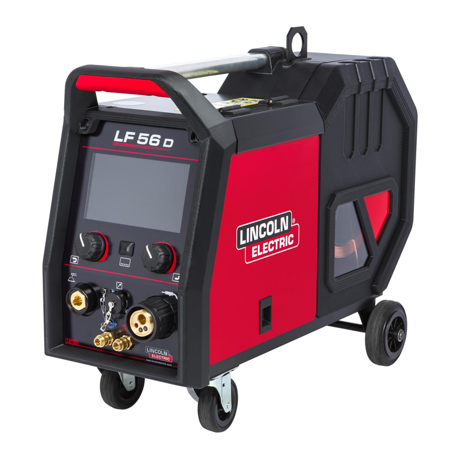
Introduction LF 56D is digital wire feeder which have been designed to Set of power source and wire feeder allow welding in work with Lincoln Electric power sources: listed processes: POWERTEC ® i350S, GMAW (MIG/MAG), ®... - Page 8 3. Quick Coupling Socket: Coolant inlet (takes Controls and Operational Features warm coolant from the welding gun). WARNING Maximum coolant pressure is 5 bar. 4. Output Socket for SMAW and CAG welding: For connecting welding cable with an electrode holder. 5.
- Page 9 User Interface Advanced (U7) 14 15 Figure 3 17. Remote Control Socket: For connecting a Remote Control (see "Accessories" chapter). Figure 4 18. USB Port: For connecting the USB memory and software updates. 19. 7ʺ display: TFT display shows welding processes parameters.
- Page 10 Figure 5. Standard view Figure 6. Advanced view 23. Status Bar. Welding Parameters Bar The Welding Parameters Bar enables: Welding process / program selection. Gun operating mode selection (2 step/4 step for GMAW, FCAW, GTAW process). Add or hide functions and welding parameters –...
- Page 11 Table 2 Default GTAW Welding Parameters Bar Table 4 Default SMAW Welding Parameters Bar Symbol Description Symbol Description Welding process / program selection Welding process / program selection Support Support Hot Start Arc Force Trigger torch operating mode (2 step/ Hot Start 4 step) Configuration...
- Page 12 Select Welding Program Welding Process To select the Welding Program: Press the button [22] or Right Control [21] to get access of Welding Parameters Bar. Press the Right Control [21] to highlight ʺWelding process / program selectionʺ. ...
- Page 13 Support User setup To access the Support Menu: To access the User Setup: Press the button [22] or Right Control [21] to get Press the button [22] or Right Control [21]. Use the access of Welding Parameters Bar. Right Control [21] to highlight the icon ʺUser setupʺ.
- Page 14 To remove selected parameter or function from the WARNING Welding Parameters Bar [29]: To change the parameters or functions value, theirs icons Access to the ʺUser Setupʺ. has to be added to the Welding Parameters Bar [29]. Use the Right Control [21] to highlight the parameter or function icon which was added to the Welding To add parameter or function to the Welding Parameters Parameters Bar [29].
- Page 15 Parameters and functions description: MECHAPULSE™ - is available for all synergy modes and produces very high quality welds Preflow Time – time that shielding gas flows with rippled seam appearance. This effect is after the torch trigger was pressed before prior achieved by combining two operating points, to wire feeding.
- Page 16 Save – the following data can be save on a Press the Right Control [21] to confirm - ʺSave to the USB Memory Stick: (Table 9): User Memoryʺ is shown on the display. Use the Right Control [21] to highlight the memory number where the program will be stored.
- Page 17 Press the Right Control [21] to get access of ʺSaveʺ To confirm and save the data on USB Memory Stick, option – the save menu is shown on the display. highlight the ʺCheck Markʺ icon and then press the Right Control [21].
- Page 18 Figure 31 Figure 34 Settings – this option allows you to load. To confirm and load the data from a USB Memory Settings, – this option allows you to load Stick, highlight the ʺCheck Markʺ icon and then press Current Welding Settings,...
- Page 19 In any case you can return to selection of files list by Left control [20] press. Figure 38 WARNING Only files provided by Lincoln Electric Company can be Highlight the file by Right Control [21] and confirm by played.
- Page 20 Limits – it allows the operator to set the limits Settings and Configuration Menu of main welding parameters in selected job. To access the Settings and Configuration Menu: The Operator is able to adjust the parameter Press the button [22] or Right Control [21] to get value within specified limits.
- Page 21 Press Right Control [21]. The ʺUI lookʺ menu is shown on the display. Figure 43 Figure 46 Use Right Control [21] to choose the parameter which Use the Right Control [21] to choose the display will be changed. configuration.
- Page 22 PIN – it allows to set the PIN. To set the PIN: Access to ʺConfiguration Menuʺ and then to ʺAccess Control Menuʺ. Use the Right Control [21] to highlight the ʺPINʺ icon. Figure 50 Press the Right Control [21]. Lock function menu is presented on the display.
- Page 23 Enable/ Disable Jobs Save - it allows to switch off/on save jobs to memory Access to ʺConfiguration Menuʺ and then to ʺAccess Control Menuʺ. Use Right Control [21] to highlight the ʺEnable/Disable Jobsʺ icon. Figure 56 Select Jobs for Job Work - it allows to choose which jobs will be enable when Job Mode will be activated.
- Page 24 Enable/ Disable Jobs Mode or Set the Language – user can choose Select Jobs for Jobs Mode – user interface language (English, Polish, Finnish, has access to operate only with French, German, Spanish, Italian, Dutch, selected jobs. Romanian, Slovak, Hungarian, Czech, Turkish, Russian, Portuguese).
- Page 25 Green Mode – is a power management feature that enables welding equipment to switch to low power state and reduce power consumption while is not using. WARNING ® ® Not apply to Flextec 350x i Flextec 500x. To adjust this functions: ...
- Page 26 Sound volume - It allows to adjust the operation sound level. To adjust this functions: Access to ʺConfiguration Menuʺ. Use the Right Control [21] to highlight the ʺVolume level icon. Press the Right Control [21]. The Volume Level Menu is shown on the display.
- Page 27 Restore Factory Setting WARNING After Factory Settings restore, the settings stored in user memory will be deleted. To restore factory settings: Access to ʺConfiguration Menuʺ. Use the Right Control [21] to highlight the ʺRestore Factory Settingsʺ icon. Figure 75 ...
- Page 28 Table 16 The Configuration Parameters The Menu Exit Exit from menu Wire Feed Speed (WFS) units Enables change WFS units: "m/min" (factory default) "in/min" Recall Memory with Trigger This option allows a memory to be recalled by quickly pulling and releasing the gun trigger: ...
- Page 29 P.17 Remote Control Type This option selects the type of analog remote control being used. "Push-Pull Gun" = Use this setting while MIG welding with a push-pull gun that uses a potentiometer for wire feed speed control. "TIG Amp Control" = Use this setting while TIG welding with a foot or hand current control device (Amptrol).
- Page 30 P.323 System Update This parameter is active when a USB memory is connected to the USB port. "Cancel" = Returns to the configuration parameters menu; "Accept" = Starts the update process. *Note: The list of available Configuration Parameters depends on the power source. English English...
- Page 31 Cooler Menu WARNING Cooler Menu is available when cooler is connected. WARNING Not apply to Flextec ® 350x and Flextec ® 500x. Figure 79 Table 19 Service Menu Symbol Description Service weld logs Figure 78 Weld History Table 17 Cooler Menu Symbol Description SnapShot...
- Page 32 SnapShot – create a file that contains detailed configuration debugging information collected from each module. This file can be sent to Lincoln Electric Support to troubleshoot any possible issues that cannot be easily resolved by the user. To obtain a SnapShot: ...
- Page 33 Procedure of beginning welding of GMAW, FCAW-GS or WARNING FCAW-SS process: Do not kink or pull cable around sharp corners. Connect a recommended Lincoln Electric power source (see ʺAccessoriesʺ chapter). By applying the principle of occupational health and ...
- Page 34 Figure 86 Pinch controls the arc characteristics when short-arc welding. Increasing Pinch Control results in a crisper arc (more spatter) while decreasing provides a softer arc (less spatter). Adjust range: from -10 to +10. Factory default, Pinch is OFF. Figure 87 English English...
- Page 35 Welding GMAW and FCAW-GS Process in synergic mode CV Table 21. Exemplify GMAW and FCAW-GS synergic programs for POWERTEC ® Wire diameter [mm] Wire material 1.32 Steel Steel ArMIX Stainless ArMIX Aluminum AlSi Aluminum AlMg Metal Core ArMIX Cored Wire Cored Wire ArMIX Si Bronze...
- Page 36 In synergic mode, the welding voltage is not set directly by user. The correct welding voltage will be set by the machine’s software. Optimal voltage value is related to the input data: Wire Feed Speed, WFS. If it is needed, the welding voltage can be adjusted by the Right Control [21].
- Page 37 Welding High Penetration Speed (HPS) Process in synergic mode Table 24 Exemplify synergic programs for HPS Wire diameter [mm] Wire material 1.32 Steel ArMIX Note: The list of available programs depends on the power source. In synergic mode, the welding voltage is not set directly by user.
- Page 38 Welding Speed Short Arc (SSA) Process in synergic mode Table 25. Exemplify synergic programs for SSA FOR SPEEDTEC ® Wire diameter [mm] Wire material 1.32 Steel ArMIX Stainless ArMIX Note: The list of available programs depends on the power source. In synergic mode, the welding voltage is not set directly by user.
- Page 39 Welding GMAW-P Process in synergic mode ® Table 26. Exemplify GMAW-P programs for SPEEDTEC Wire diameter [mm] Wire material 1.32 Steel ArMIX Stainless ArMIX Metal Core ArMIX Aluminum AlSi Aluminum AlMg Cored Wire ArMIX Table 27. Exemplify GMAW-P programs for FLEXTEC ®...
- Page 40 Figure 99 UltimArc™ – for pulse welding adjusts the focus or shape of the arc. In consequence of increasing UltimArc™ Control value the arc is tight, stiff for high speed sheet metal welding. Adjust range: from -10 to +10 ...
- Page 41 Welding Soft Silence Pulse (SSP ) Process in synergic mode Table 28. Exemplify synergic programs for SSA FOR SPEEDTEC ® Wire diameter [mm] Wire material 1.32 Steel ArMIX Stainless ArMIX Note: The list of available programs depends on the power source. modified especially pulse...
- Page 42 Frequency – for pulse welding adjusts the focus or shape of the arc. In consequence of increasing Frequency control value the arc is tight for high speed sheet metal welding. Adjust range: from -10 to +10 Factory default, frequency is OFF. Figure 105 Figure 106 1.
- Page 43 MECHAPULSE™ function MECHAPULSE™ function produces very high quality welds with rippled seam appearance. This effect is achieved by combining two operating points, two different wire feed speeds related to different arc welding power. This function is especially recommended for welding aluminum and thin materials.
- Page 44 TUNE in pulse processes – the arc length is adjusted by TUNE1 and TUNE2. Regulation range for pulse process: from 0.50 to 1.50 of nominal value. Default TUNE value: 1.00 (the nominal setting). 0.50 1.00 1.50 Figure 113 TUNE in short arc processes (CV) regulates the voltage levels at the higher TUNE1 and lower TUNE2 working points.
- Page 45 Default value: 0 (OFF). Procedure of begin welding of SMAW process: Connect Lincoln Electric source to wire feeder (mentioned in Introduction chapter). Determine the electrode polarity for the electrode to be used. Consult the electrode data for this information.
- Page 46 Note: 4-Step does not work during Spot Welding. power source. Procedure of begin welding of GTAW/GTAW-PULSE process: Connect Lincoln Electric power source that is using for communication CAN protocol. Connect GTAW torch to Euro Socket [1]. Note: To connect GTAW torch, adapter TIG-EURO has to be purchased (See "Accessories"...
- Page 47 Pulse Period influences the width of the arc and the amount of heat input to the weld. If the value of parameters is lower: Improves penetration and the microstructure of the weld. The arc is narrower, more stable. ...
- Page 48 Gouging Table 32. The Welding Program – gouging Program number ® ® ® Process Powertec Speedtec Flextec Gouging Note: The list of available programs depends on the power source. For 9th program can set: Gouging current. Switch on / switch off the output voltage on the output lead.
- Page 49 Turn the input power off before installation or changing drive rolls. Wire Feeders LF 56D is equipped with drive roll V1.0/V1.2 for steel wire. For others wires and sizes it is required to install proper drive rolls kit (see "Accessories" chapter)
- Page 50 Lock 4 new rolls by turning 4 Quick-Change Carrier Open the gas cylinder valve. Gear [33]. Adjust the shielding gas flow of the gas regulator. Insert the wire through the guide tube, over the roller Check gas flow with Gas Purge Switch [12].
- Page 51 We respond to our customers based on the best warranty information in our possession at that time. Lincoln Electric is not in a position to warrant or guarantee such advice, Any noticeable damage should be reported immediately and assumes no liability, with respect to such information and repaired.
- Page 52 Error Table 33 Interface Components Interface description 39. Error code 40. Error description. DESCRIPTION: Thermal Overload Figure 125 Table 34 shows list of basic errors that can appear. To get full list of error codes, please contact with authorize Lincoln Electric service.
-
Page 53: Weee
12/05 Part List reading instructions Do not use this part list for a machine if its code number is not listed. Contact the Lincoln Electric Service Department for any code number not listed. Use the illustration of assembly page and the table below to determine where the part is located for your particular code machine. -
Page 54: Accessories
Accessories OPTIONS & ACCESSORIES K14204-1 WIRE FEEDER DRUM QUICK CONNECTOR K14175-1 GAS FLOW METER KIT K10095-1-15M REMOTE CONTROL 6-PINS, 15M K2909-1 6-PIN/12-PIN ADAPTER K14091-1 REMOTE MIG LF 45 PWC300-7M (CS/PP) E/H-400A-70-5M ELECTRODE HOLDER 400A/70MM² - 5M K10158-1 ADAPTER FOR SPOOL TYPE B300 K10158 ADAPTER FOR SPOOL TYPE B300 R-1019-125-1/08R... - Page 55 ROLL KIT FOR CORED WIRES KP14150-V12/16R ROLL KIT 1.2/1.6RT FI37 4PCS ORANGE/YELL KP14150-V14/20R ROLL KIT 1.4/2.0RT FI37 4PCS KP14150-V16/24R ROLL KIT 1.6/2.4RT FI37 4PCS YELL/GREY KP14150-V09/11R ROLL KIT 0.9/1.1RT FI37 4PCS KP14150-V10/12R ROLL KIT 1.0/1.2RT FI37 4PCS -/ORANGE WIRE GUIDES 0744-000-318R WIRE GUIDE SET BLUE Ø0.6-1.6 0744-000-319R...
-
Page 56: Connection Configuration
Connection configuration English English... - Page 57 English English...
- Page 58 English English...
Need help?
Do you have a question about the LF 56D and is the answer not in the manual?
Questions and answers