Table of Contents
Advertisement
Advertisement
Table of Contents

Subscribe to Our Youtube Channel
Related Manuals for VDO SUMLOG


Summary of Contents for VDO SUMLOG
-
Page 2: Table Of Contents
Spare parts ........27 The functions of the VDO Sumlog . -
Page 4: Preface
VDO Sumlog. Please take the time to study this manual completely. Your VDO Kienzle agent will be pleased to help you, if you have any fur- ther questions or problems. VDO Kienzle Vertrieb und Service GmbH ©... -
Page 5: Safety Instructions
They are an indication of particular importance regarding the operation of the system and for your safety. Good seamanship is essential! The use of the sumlog does not relieve you of your responsibility for your ship. Always use your personal seafaring experience when interpreting the displayed values. -
Page 6: For Maintenance
The use of non-insula- ted wires and contacts is strictly forbidden. Safety Instructions concerning the maintenance Repairs to the components of the sumlog system may only be made by specialists authorized by VDO Kienzle. The system fulfills the applicable safety regulations. -
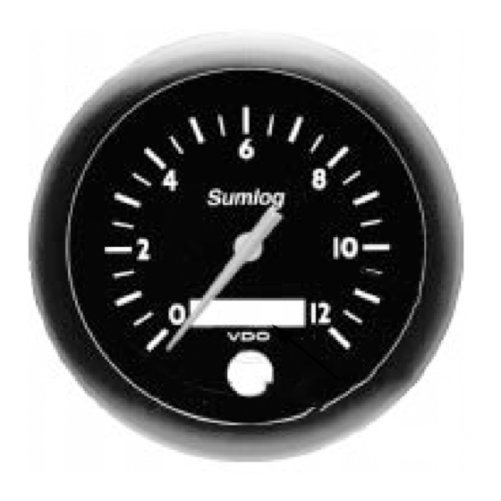
Page 7: The Vdo Sumlog
Analog scale Display Pushbutton The VDO Sumlog is an advanced speed measuring system, designed for sport navigation. The pointer displays the speed on an analog scale when the system is active. The total distance or the trip distance travelled is shown by the display in the lower dial section. -
Page 8: System Components
The system, as supplied, consists of: Indicating instrument Union nut for indicating instrument fixation Sumlog sending unit with paddle wheel and cable, length 1 m Connecting cable between sending unit and indicating unit, length 10 m Hull sleeve for Sumlog sending unit, with sealing washers and... -
Page 9: The Functions Of The Vdo Sumlog
5 seconds when the trip distance is displayed. Calibration of the VDO Sumlog After installation of the system your VDO Sumlog must be calibrated to obtain speed and distance measurements with the maximum accuracy. Mark two distinct points on the map. The distance between these two points defines the measuring length (see page 29). - Page 10 CALIBRATION Measuring length: Make a measuring run at a cruising speed, which remains as constant as possible. Check that the calibration factor is C=1.00 (as supplied) at the beginning of the measuring run, and that the trip distance counter is set to zero. The following example refers to a measuring run in water without a cur- rent with a measuring length of 2 nautical miles (nm).
- Page 11 Effectively covered distance (A-B) + (C-D) ------------------------------------------------------------ Indication of the display (A-B) + (C-D) Do not use the GPS navigator as a reference for VDO Sumlog calibration. The GPS Navigator indicates speed over ground (SOG), but the VDO Sumlog measures speed...
-
Page 12: Troubleshooting
- Paddle wheel direction not optimised,check installation. - Recalibrate unit. Maintenance of the VDO Sumlog The indicating unit is maintenance-free. Use a humid, lint-free or antista- tic cloth for cleaning. Do not use cleaning detergents. On the sending unit, check the paddle wheel and the paddle wheel shaft for wear once per season. -
Page 13: Installation Of The System
INSTALLATION Installation of the VDO Sumlog system Please read the safety instructions on pages 24 and 25 prior to the installation. Installation of the indicating unit Drill a hole, 86 mm dia., at an suitable location. Clean the material and remove any chips before inserting the indi- cating instrument. -
Page 14: Installation Of The Sending Unit
The sending unit must be installed in a turbulence-free zone in the hull. If an echo sounder is installed, the Sumlog sending unit should be instal- led at the same height and to the side of, or laterally offset to the echo- sounder. - Page 15 INSTALLATION expected. An ideal installation is near the longitudinal axis of the ship and in the zone of the first stringer, directly in front of the engine compartment if possible. At higher speeds this is the only location where a disturbance- free operation can be expected.
-
Page 16: Removal Of The Sending Unit
INSTALLATION Install flooding valve and sending unit: Put the loop of the control rope around the hull sleeve and knot the loose end of the rope to the blind plug. Screw the flood valve to the hull sleeve until an audible click indi- cates secure seating, is heard. -
Page 17: Replacement Of The Paddle Wheel
INSTALLATION Replacement of the paddle wheel The paddle wheel of the sending unit is rota- ted by the flow of water. The rotational speed of the paddle wheel is measured without contacts, and transmitted to the indi- cating instrument. Use a screwdriver to replace the paddle wheel and its shaft. -
Page 18: Electrical Installation
INSTALLATION Electrical installation System power supply Illumination... -
Page 19: Connection Of A Repeater Display Unit
INSTALLATION Connection of a repeater display unit Make the power supply connection for the repeater the same as the main unit (s.p. 37). The connection between the main unit and the repeater is shown in the diagram below. Main unit Repeater Note that the calibration factor C must also be set (see page... -
Page 20: Circuit Diagram Legend
INSTALLATION / DATA Circuit diagram legend: On/Off switch for navigation instruments On/Off switch for instrument lighting Fuse for navigation instruments (5 A) Fuse for instrument lighting (5 A) Recommended cable section: 1.5 mm Cable lengths: Log sending unit - Indicating instrument 20 m max.
Need help?
Do you have a question about the SUMLOG and is the answer not in the manual?
Questions and answers
how can I remove and replace the glass front of the sumlog?