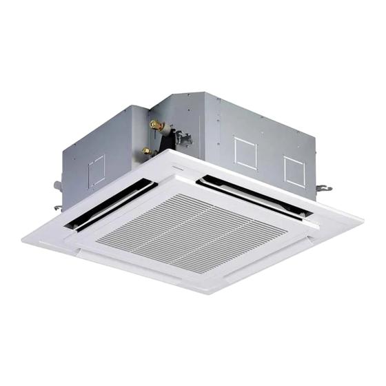
Table of Contents
Advertisement
Quick Links
Advertisement
Table of Contents
Troubleshooting

Summarization of Contents
SAFETY CAUTION
Definition of Qualified Installer or Service Person
Defines requirements for installers and service personnel regarding qualifications and knowledge.
Definition of Protective Gear
Specifies required protective gear for various work activities to ensure safety.
Meaning of Symbols Displayed on the Unit
Explains the meaning of various warning and informational symbols found on the unit.
Warning Indications on the Air Conditioner Unit
Details warning labels and their descriptions found on the air conditioner unit.
Precautions for Safe Operation
Covers essential safety rules, electrical hazards, and general operational precautions.
General Safety Guidelines and Prohibitions
Covers essential safety rules, electrical hazards, and general operational precautions.
SPECIFICATIONS
Model Specifications and Performance Data
Provides detailed technical specifications for cooling/heating capacity, power, and electrical characteristics.
Refrigerant R32 Safety and Handling
Outlines safety precautions, cautions, and pipe material requirements for R32 refrigerant.
Required Tools for R32 Installation
Lists specific tools required for R32 refrigerant handling and installation.
CONSTRUCTION VIEWS (EXTERNAL VIEWS)
Indoor Unit Dimensions and Installation Space
Illustrates indoor unit dimensions, installation clearances, and space requirements.
Indoor Unit Component Layout
Details the layout of ports, electrical boxes, and knockout holes on the indoor unit.
SYSTEMATIC REFRIGERATING CYCLE DIAGRAM
Unit Configuration Diagrams (Single, Twin, Triple, Double-Twin)
Presents diagrams for single, twin, triple, and double-twin unit system configurations.
WIRING DIAGRAM
Indoor Unit Wiring Schematics
Provides detailed wiring diagrams for the indoor unit and its components.
SPECIFICATIONS OF ELECTRICAL PARTS
Indoor Unit Component Specifications
Lists specifications for electrical components like fan motors, sensors, and switches.
INDOOR CONTROL CIRCUIT
Indoor Controller Block Diagram and Connections
Illustrates the indoor controller's block diagram and connection methods for remote controllers.
Control Specifications and Operation Modes
Details control specifications, operation modes, and temperature settings.
Indoor Print Circuit Board Layout
Shows the layout and connection points of the indoor unit's main circuit board.
TROUBLESHOOTING
Summary of Troubleshooting Procedures
Provides an overview of troubleshooting steps, required tools, and initial checks.
Troubleshooting Check Code Lists (Indoor & Communication)
Lists check codes for indoor unit and communication-related errors with causes.
Diagnostic Procedures for Specific Check Codes
Offers step-by-step diagnostic flowcharts for common indoor unit error codes.
REPLACEMENT OF SERVICE P.C. BOARD
P.C. Board Replacement Procedures
Details the step-by-step procedures for replacing the indoor unit's main P.C. board.
SETUP AT LOCAL SITE AND OTHERS
Indoor Unit Test Run and Function Setup
Covers test run procedures and various function setup options via remote controller.
1:1 Model Connection Interface Setup
Explains the setup and wiring for the 1:1 model connection interface for central control.
Address Setup and Group Control
Details address setup procedures for single, twin, and group operations.
Manual Address Setup via Remote Controller
Provides instructions for manually setting addresses using the remote controller.
MAINTENANCE / CHECK LIST
Regular Maintenance Schedule and Procedures
Outlines recommended maintenance checks and cleaning procedures for optimal system performance.
DETACHMENTS
Suction Grille Removal and Installation
Step-by-step guide for detaching and attaching the suction grille.
Electric Parts Cover Removal and Installation
Instructions for removing and installing the electric parts cover.
Adjust Corner Cap Removal and Installation
Procedure for detaching and attaching the adjust corner cap.
Ceiling Panel Removal and Installation
Detailed steps for removing and installing the ceiling panel.
Control P.C. Board Replacement
Instructions for detaching and attaching the control P.C. board.
Drain Cap Removal and Installation
Procedure for removing and installing the drain cap.
Fan Motor Removal and Installation
Step-by-step guide for removing and installing the fan motor assembly.
Drain Pump Removal and Installation
Instructions for detaching and attaching the drain pump.
Float Switch Assembly Removal and Installation
Procedure for removing and installing the float switch assembly.
Heat Exchanger Removal and Installation
Detailed steps for removing and installing the heat exchanger.
EXPLODED VIEWS AND PARTS LIST
Indoor Unit Exploded View and Parts List
Provides exploded views and part numbers for the indoor unit components.
Electric Parts List
Lists part numbers for various electric components used in the indoor unit.
WARNINGS ON REFRIGERANT LEAKAGE
Refrigerant Concentration Limits and Safety Measures
Details concentration limits for R32 refrigerant and necessary safety measures.


Need help?
Do you have a question about the RAV-HM801UTP Series and is the answer not in the manual?
Questions and answers