Table of Contents

Related Manuals for Boonton 9242


Summarization of Contents
1. General Information
1.1 Organization
Describes the manual's seven sections and three appendices.
1.2 Description
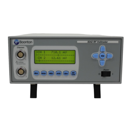
Details the Model 9240 RF Voltmeter's capabilities and frequency range.
1.3 Features
Lists key features like software, alphanumeric display, and dual channels.
1.4 Accessories
Lists optional accessories available for the 9240 Series.
1.5 Models, Options and Configurations
Explains different models (9241, 9242) and available options.
1.6 Specifications
Presents performance specifications including voltage probe inputs and features.
2. Installation
2.1 Unpacking & Repacking
Provides instructions for unpacking the instrument and its components.
2.2 Power Requirements
Details the power supply specifications and connection procedures.
2.3 Connections
Explains how to connect probes, recorders, and remote interfaces.
2.4 Preliminary Check
Outlines steps to verify instrument operation and software installation.
3. Getting Started
3.1 Organization
Identifies objects on panels, display organization, and initial configuration.
3.2 Operating Controls, Indicators and Connections
Illustrates and describes front and rear panel controls, indicators, and connectors.
3.3 Operation
Describes instrument configuration via front panel controls and menus.
4. Operation
4.1 Zeroing the Instrument
Explains automatic zeroing to ensure measurement accuracy.
4.2 Making Measurements
Describes how to connect the probe and display voltage or dB levels.
4.3 Overload Limits
Details overload protection for probes and adapters to prevent damage.
4.4 Connection Recommendations
Advises on proper probe tip and adapter usage for accurate measurements.
4.5 Low Level Measurements
Discusses achieving accurate measurements for very low signal levels.
4.6 Temperature Effects
Explains how temperature variations can affect measurement accuracy.
4.7 Hum, Noise and Spurious Pickup
Advises on precautions to avoid measurement errors from external interference.
4.8 Recorder Output
Describes the DC output for connecting to external recorders.
4.9 Correction Curve for Model 952003 50 Ohm Type N Tee Adapter
Provides correction factors for using the 952003 Tee Adapter.
4.10 Correction Curve for Model 952007 75 Ohm Type N Tee Adapter
Provides correction factors for using the 952007 Tee Adapter.
4.11 RF Power Measurements
Explains how to perform power calculations using the Zo function.
5. Remote Operation
5.1 GPIB Configuration
Configures the instrument for GPIB communication.
5.2 RS-232 Configuration
Configures the instrument for RS-232 serial communication.
5.3 SCPI Language
Details the SCPI programming conventions used for remote control.
5.4 Basic Measurement Information
Explains using MEASure commands for obtaining readings.
5.5 SCPI Command Reference
Lists and describes all SCPI remote commands accepted by the 9240 Series.
6. Maintenance
6.1 Safety
General safety precautions for operation and maintenance.
6.2 Cleaning
Instructions for cleaning the instrument's painted surfaces.
6.3 Inspection
Visual inspection procedure for instrument malfunctions.
6.4 Firmware Upgrade
Information on updating the instrument's firmware.
6.5 Firmware Upgrade Instructions
Step-by-step guide for upgrading instrument firmware using specific software.
7. Appendix A SCPI Error Messages
7.1 SCPI Error Messages
Lists SCPI error codes and their descriptions.
8. Appendix B Warranty & Repair
Repair Policy
Outlines procedures for instrument and probe repair.
Limited Warranty
Details the warranty terms for instruments and probes.
Need help?
Do you have a question about the 9242 and is the answer not in the manual?
Questions and answers