
Related Manuals for Boonton PMX40


Summary of Contents for Boonton PMX40
- Page 1 PMX40 RF Power Meter – INSTRUCTION MANUAL INSTRUCTION MANUAL PMX40 RF Power Meter 98408900A | Rev 20210115...
- Page 3 Parsippany, NJ, USA. All rights reserved. P/N 98408900A This manual covers the PMX40 RF Power Meter, serial numbers: 1001 and higher. The PMX40 application software used in this product is licensed by Boonton Electronics, a subsidiary of the Wireless Telecom Group, Inc.
- Page 4 Failure to comply with these precautions or with specific warnings elsewhere in this manual violates safety standards of design, manufacture, and intended use of the instrument. Boonton Electronics assumes no liability for the customer’s failure to comply with these requirements.
- Page 5 PMX40 RF Power Meter – INSTRUCTION MANUAL SAFETY SYMBOLS This safety requirement symbol has been adopted by the International Electro-technical Commission, Document 66 (Central Office) 3, Paragraph 5.3, which directs that an instrument be so labeled if, for the correct use of the instrument, it is necessary to refer to the instruction manual.
-
Page 6: Table Of Contents
PMX40 RF Power Meter – INSTRUCTION MANUAL Contents General Information .......................... 1-1 Organization ..........................1-1 Description ..........................1-2 Features ............................. 1-2 Accessories ..........................1-2 Optional Configurations ......................1-2 Specifications ..........................1-2 Installation ............................2-1 Unpacking & Repacking ......................2-1 Power Requirements ......................... 2-2 Connections .......................... - Page 7 PMX40 RF Power Meter – INSTRUCTION MANUAL 4.4.7 MAINTrigger ........................4-8 4.4.8 MAINMarkers ......................... 4-9 4.4.9 MAINPulse Def ......................4-10 4.4.10 MAINSystem ......................... 4-11 4.4.11 MAINSystemSensor Data ..................4-11 4.4.12 MAINSystemI/O ConfigLAN .................. 4-12 4.4.13 MAINSystemTest Source ..................4-12 4.4.14 MAINSystemExit .......................
-
Page 9: General Information
1 General Information This instruction manual provides you with the information you need to install, operate, and maintain the Boonton PMX40 RF Power Meter. Section 1 is an introduction to the manual and the instrument. 1.1 Organization The manual is organized into five sections and two Appendices, as follows: Section 1 - General Information presents summary descriptions of the instrument and its principal features, accessories, and options. -
Page 10: Description
RF power in both the time and statistical domains through an intuitive, touch screen display. The PMX40 RF Power Meter utilizes up to four Boonton USB RF power sensors with industry-leading performance and capabilities either independently or for synchronized multi-channel measurements of CW, modulated, and pulsed signals. -
Page 11: Installation
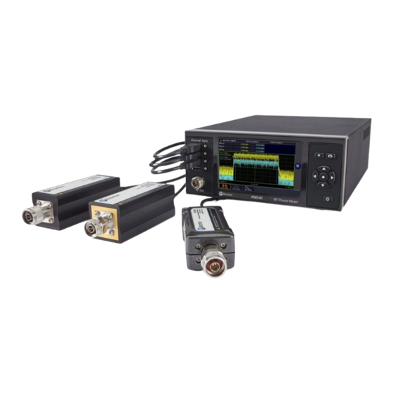
2.1 Unpacking & Repacking The PMX40 RF Power Meter is shipped complete and is ready to use upon receipt. Figure 2-1 shows you the various pieces included in the packaging and the order in which they are loaded into the container. -
Page 12: Power Requirements
2.2 Power Requirements The PMX40 is equipped with a switching power supply that provides automatic operation from a 90 to 264 VAC, 47 to 63 Hz single-phase, AC power source. Maximum power consumption is 70 VA. Connect the power cord supplied with the instrument to the power receptacle on the rear panel. See Figure 3-2. -
Page 13: Preliminary Check
PMX40 RF Power Meter – INSTRUCTION MANUAL 2.4 Preliminary Check The following preliminary check verifies that the instrument is operational and has the correct software installed. It should be performed before the instrument is placed into service. To perform the preliminary check, proceed as follows: Press the lower half (marked "0") of the power switch in the center of the power module on the... - Page 14 PMX40 RF Power Meter – INSTRUCTION MANUAL Note The base PMX40 model only permits two sensors to be active at any one time. With the PMX40-4CH option, four sensors can be active at any one time. On the front panel, press the key to bring up the on-screen menu. From the Main menu, use the touch screen or the ◄, ►, ▲, ▼, and ...
-
Page 15: Getting Started
PMX40 RF Power Meter – INSTRUCTION MANUAL 3 Getting Started This chapter will introduce the user to the PMX40 RF Power Meter. The chapter will identify objects on the front and rear panels, identify display organization, list the configuration of the instrument after initializing, and provide practice exercises for front panel operation. - Page 16 Sensor Inputs Four sensor inputs are located on the front and rear panels of the instrument. These are standard USB 2.0 Type A receptacles designed to accept only Boonton power sensors or standard USB keyboards, mice, and flash drives. Trigger Inputs Four sensor trigger inputs are located on the front and rear panels of the instrument.
- Page 17 PMX40 RF Power Meter – INSTRUCTION MANUAL current instrument state before shutdown. Pressing and holding the On/Standby key for several seconds will force standby mode if the instrument has become non-responsive. In this case, no context save is performed. Cooling Fan...
-
Page 18: Touch Screen Display
The PMX40 RF Power Meter can be completely controlled through the touch screen display and by use of the front panel buttons. Table 3-2 describes the different areas of the display layout of the PMX40 RF Power Meter. Figure 3-3 shows the Graph Display mode of the instrument using the Pulse Measure mode with a menu exposed. - Page 19 This area indicates which channels are ON and their individual scale and vertical center. Note The base PMX40 model only permits two sensors to be active at any one time. With the PMX40-4CH option, four sensors can be active at any one time.
-
Page 20: Initialization
Figure 3-4. PMX40 Graph Display Using Pulse Measure Mode With Menus Hidden 3.4 Initialization The steps shown here will initialize the PMX40 meter and prepare it for normal operations. Step 3 should only be performed when you wish to set the meter operations to a known state. This is typically done when you first power on the instrument or at the start of a new test. - Page 21 PMX40 RF Power Meter – INSTRUCTION MANUAL Note Connecting the Sync cable from the Multi I/O port on the sensor to the corresponding Sync port on the instrument for the sensor in use is necessary if using an external trigger or when performing measurements across multiple channels.
-
Page 22: Making Measurements
PMX40 RF Power Meter – INSTRUCTION MANUAL Parameters Related to the Markers Menu Marker 1 -300 uS Marker 2 300 uS Parameters Related to the Pulse Def. > CH# Pulse Def > Menus Distal Mesial Proximal Pulse Units Watts Start Gate 5.00%... -
Page 23: Pulse Mode
For periodic or pulsed signals, it is often necessary to analyze the power for a portion of the waveform, or a certain region of a pulse or pulse burst. For these applications, the PMX40 Series has a triggered Pulse mode. -
Page 24: Statistical Mode
Statistical mode is only available when using peak power sensors with the PMX40. It is the best choice for analyzing signals with a high crest factor, that are noise-like with random or infrequent peaks, or are modulated in a random, non-periodic fashion. - Page 25 PMX40 RF Power Meter – INSTRUCTION MANUAL • Moderate signal level (above about -40 dBm except when modulation is off). Noise-like digitally modulated signals such as CDMA (and all its extensions) or OFDM when • probability information is helpful in analyzing the signal.
- Page 26 PMX40 RF Power Meter – INSTRUCTION MANUAL Figure 3-8. CCDF Plot With Menu Showing Cursor at 1% Note that this analysis does not depend upon any particular test signal, or upon synchronization with the modulating signal. In fact, the analysis can be done using actual communication system signals.
-
Page 27: Operation
key to select the entry or by use of the touch screen. The PMX40 RF Power Meter base model only permits two sensors to be active at any one time. With the PMX40-4CH option, four sensors can be active at any one time. In the Menu Reference that follows the designation "Channel#"... -
Page 28: Parameter Data Entry And Selection
PMX40 RF Power Meter – INSTRUCTION MANUAL 4.3 Parameter Data Entry and Selection The PMX40 RF Power Meter parameters can be changed in various ways depending on the type of parameter being addressed. 4.3.1 Numerical Data Entry Numerical data can be incremented/decremented by selecting the “+” and “–“ icons with the front panel keys or by touching them. -
Page 29: Menu Reference
4.4.2 MAINMeasure Measurement: The state of the data acquisition mode for taking measurements. If Measurement is set to Run, the PMX40 immediately begins taking measurements (Continuous and Statistical modes), or arms its trigger and takes a measurement each time a trigger occurs (Pulse Mode). If set to... -
Page 30: MainDisplay
PMX40 RF Power Meter – INSTRUCTION MANUAL Single Sweep: Only available in Pulse mode. Select to start a single measurement cycle in Pulse mode when Measurement is set to Stop. Enough trace sweeps must be triggered to satisfy the channel averaging setting. -
Page 31: MainChannel
4.4.5 MAINChannel Channel#: Opens the settings menu for the selected channel. Note The base PMX40 model only permits two sensors to be active at any one time. With the PMX40-4CH option, four sensors can be active at any one time. MAINChannelChannel# Chan. - Page 32 PMX40 RF Power Meter – INSTRUCTION MANUAL Averaging: Only available in Pulse and Statistical modes. Set the number of traces averaged together to form the measurement result on the selected channel. Averaging can be used to reduce display noise on both the visible trace, and on marker and automatic pulse measurements.
- Page 33 At other levels, that gain setting is combined with stored linearity factors to compute the actual power. Caution The built-in test source of the PMX40 is not a sufficiently calibrated source for performing a fixed calibration. An external calibration source is required. Note that fixed calibration is NOT REQUIRED for USB power sensors.
-
Page 34: MainTime
PMX40 RF Power Meter – INSTRUCTION MANUAL 4.4.6 MAINTime Timebase: Controls the timebase or horizontal scale of the acquisition and is noted on the horizontal axis label of the Trace View. The Timebase pulldown menu permits selection of fixed timebase ranges from 5 ns/div to 50 ms/div (sensor series dependent) in a 1-2-5 progression. -
Page 35: MainMarkers
RF input. The external trigger is attached to the Trig In BNC connector on the rear of the PMX40 Power Meter and requires a TTL signal level, minimum pulse width of 10 ns, and maximum frequency of 50 MHz. -
Page 36: MainPulse Def
PMX40 RF Power Meter – INSTRUCTION MANUAL 4.4.9 MAINPulse Def CH# Pulse Def: Opens the Pulse Definition menu for the selected channel. MAINPulse DefCH# Pulse Def Distal: Sets the pulse amplitude percentage that defines the end of a rising edge or beginning of a falling edge transition. Typically, this is 90% voltage or 81% power relative to the top level of the pulse. -
Page 37: MainSystem
PMX40 RF Power Meter – INSTRUCTION MANUAL measurements between mesial crossings such as width and period are not affected. The purpose of the Pulse Gate setting is to exclude edge transition effects from the pulse power measurements. 4.4.10 MAINSystem The System menu displays the available system-level features and functionality. -
Page 38: MainSystemI/O ConfigLan
Enable or Disable the output of the built-in 0 dBm 50 MHz test source. Caution The built-in test source of the PMX40 is not a sufficiently calibrated source for performing a fixed calibration. An external calibration source is required. 4-12... -
Page 39: MainSystemExit
Update Software: Select Go to search the connected USB drive for the *.tar software update file and update or re-install the version found. If no valid file is found, the dialog in Figure 4-6 appears and the PMX40 does nothing. -
Page 41: Application Notes
PMX40 RF Power Meter – INSTRUCTION MANUAL 5 Application Notes This section provides supplementary material to enhance your knowledge of Model PMX40 operation, advanced features, and measurement accuracy. Topics covered in this section include pulse measurement fundamentals, automatic measurement principles, and an analysis of measurement accuracy. - Page 42 Figure 5-1. Pulsed RF Signal Figure 5-2. Distorted Pulsed Signal Peak Power. The Model PMX40 makes power measurements in a manner that overcomes the limitations of the pulse power method and provides both peak power and average power readings for all types of modulated carriers.
-
Page 43: Diode Detection
PMX40 RF Power Meter – INSTRUCTION MANUAL averaging, the Model PMX40 has additional capabilities that allow it to perform statistical analysis on a complete set of continuously sampled data points. Data can be viewed and characterized using a CCDF presentation format. These analysis tools provide invaluable information about peak power levels and their frequency of occurrence, and are especially useful for non-repetitive signals, such as those used in 5G and Wi-Fi applications. -
Page 44: Pulse Definitions
IEEE Std 194™-1977 Standard Pulse Terms and Definitions “provides fundamental definitions for general use in time domain pulse technology.” Several key terms defined in the standard are reproduced in this subsection, which also defines the terms appearing in the PMX40 text mode display of automatic measurement results. -
Page 45: Standard Ieee Pulse
PMX40 RF Power Meter – INSTRUCTION MANUAL 5.2.1 Standard IEEE Pulse The key terms defined by the IEEE standard are abstracted and summarized below. These terms are referenced to the standard pulse illustrated in Figure 5-4. Figure 5-4. IEEE Standard Pulse (IEEE Std 194™-1977) Note IEEE Std 194™-1977 Standard Pulse Terms and Definitions has been superseded by IEEE... -
Page 46: Automatic Measurements
5.3.2 Automatic Measurement Terms The following terms appear in the PMX40 Text display in the Pulse mode. The Text column lists the abbreviated forms that appear on the display screen. -
Page 47: Automatic Measurement Sequence
PMX40 RF Power Meter – INSTRUCTION MANUAL Fall Falltime The interval between the last signal crossing of the distal line to the last signal crossing of the proximal line. Period Pulse Period The interval between two successive pulses (reciprocal of the Pulse Repetition Frequency). - Page 48 PMX40 RF Power Meter – INSTRUCTION MANUAL Starting at the left edge of the screen, the processor classifies each Transition threshold crossing according to whether it is positive-going (– +) or negative-going (+ –). Because the signal is repetitive, only three transitions are needed to classify the waveform, as follows:...
- Page 49 PMX40 RF Power Meter – INSTRUCTION MANUAL The process establishes the proximal, mesial, and distal levels as a percentage of the difference between top amplitude and bottom amplitude power. The percentage can be calculated on a power or voltage basis. The proximal, mesial, and distal threshold values are user settable from 1% to 99%, with the restriction that the proximal <...
-
Page 50: Average Power Over An Interval
PMX40 RF Power Meter – INSTRUCTION MANUAL The processor computes the rise and/or fall times of waveforms that meet the following conditions: The waveform must have at least one usable edge (Types 2 through 7). The signal peak must be at least 13 dB greater than the minimum sample value. -
Page 51: Statistical Mode Automatic Measurements
The signal excursion must be at least 6 dB. 5.4 Statistical Mode Automatic Measurements When operating in Statistical mode, the PMX40 has a unique text format display that is available when the TEXT/GRAPH system key is pressed. A sample of the text display is shown in Figure 5-8. - Page 52 PMX40 RF Power Meter – INSTRUCTION MANUAL Table 5-3. Statistical Automatic Measurements In the Statistical mode the following five automatic measurements are displayed in the PMX40 Text display for both input channels and both trigger channels. The Text column lists the abbreviated forms that appear on the display screen.
-
Page 53: Measurement Accuracy
5.5 Measurement Accuracy The measurement accuracy of the PMX40 is completely contingent upon the USB sensor with which it is being used. Please reference the sensor datasheet and/or associated uncertainty calculator for measurement uncertainties associated with a specific sensor. -
Page 55: Maintenance
6.3 Inspection If the PMX40 malfunctions, perform a visual inspection of the instrument. Inspect for signs of damage caused by excessive shock, vibration, or overheating. Inspect for broken wires, loose electrical connections, or accumulations of dust or other foreign matter. -
Page 56: Lithium Battery
Figure 6-1. Self-Test Results Lithium Battery The PMX40 contains one Lithium “coin cell” battery to provide for non-volatile storage of the instrument state. This is located on the Main Printed Circuit assembly. It should have a life of 5-10 years. When replacement is necessary, the battery must be disposed of in strict compliance with local environmental regulations. -
Page 57: Appendix A - Warranty And Repair Policy
Appendix A - Warranty and Repair Policy Model PMX40 Instrument If the Boonton Model PMX40 RF Power Meter is not operating correctly and requires service, contact the Boonton Electronics Service Department for return authorization. You will be provided with an RMA number and shipping instructions. -
Page 59: Appendix B - End User License Agreement
PMX40 RF Power Meter – INSTRUCTION MANUAL Appendix B - End User License Agreement Available upon written request. -- END -- PMX40 RF POWER METER INSTRUCTION MANUAL APPENDIX B-1...
Need help?
Do you have a question about the PMX40 and is the answer not in the manual?
Questions and answers