
Subscribe to Our Youtube Channel
Related Manuals for Boonton 8201A


Summary of Contents for Boonton 8201A
- Page 1 8201A Modulation Analyzer Quick Start Guide Taking performance to a new peak PN: 98407700A...
- Page 2 Typical measurement situations are also described. The 8201A is an updated version of the discontinued Model 8201. The 8201A is fully compatible with the 8201 - the two models have identical operation and specifications.
- Page 3 Content Safety and Caution summary ..................4 Limited Warranty ......................4 Instrument Displays and Operating Controls ............. 5 Getting Started ......................... 5 Getting familiar with Function Keys................10 Getting familiar with Data Keypad ................10 Getting familiar with Measurement Control Keys ...........11 Other Keys ........................12 Displayed Messages .......................13 Special Functions ......................13...
-
Page 4: Limited Warranty
OTHER WARRANTIES, EXPRESSED OR IMPLIED, INCLUDING, BUT NOT LIMITED TO, THE IMPLIED WARRANTIES OF MERCHANTABILITY AND FIT- NESS FOR A PARTICULAR PURPOSE. Boonton will not be liable for any CAUTION incidental damages or for any consequential damages, as defined in Section 2-715 of the Uniform Commercial Code, in connection with • Please check the power requirements as per the product specifica-... -
Page 5: Getting Started
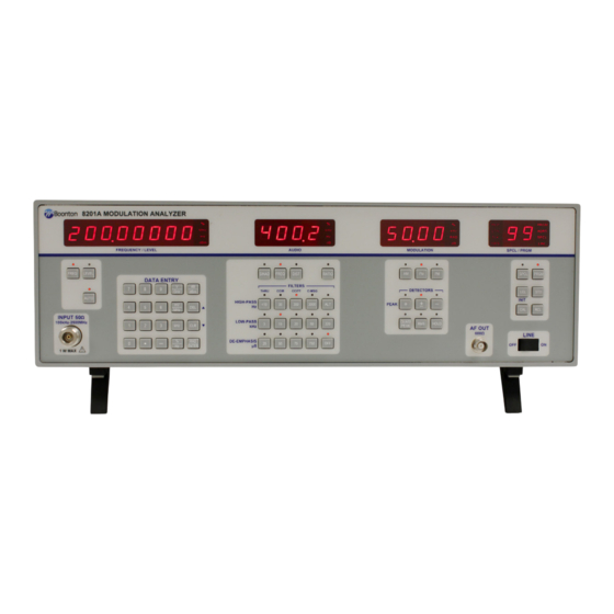
Instrument Displays & Operating Controls Getting Started The 8201A instrument displays are shown as below in Figure-1. The The following instructions walk through a basic operation and func- front panel of the Model 8201A is organized for simple instrument tionality tests to verify that the unit is working properly. - Page 6 Figure-2: Front View of 8201A Modulation Analyzer Table-1: Controls, Displays and Connectors of Front Panel of 8201A Modulation Analyzer (Fig-2) Control, Indicator Or Connector Index Number Function FREQUENCY/LEVEL display Displays carrier frequency in kHz or MHz, and RF level in dBm or mV. Alternately displays error codes and messages.
- Page 7 Control, Indicator Or Connector Index Number Function DATA ENTRY keys: 0 – 9 keys Number entry keys. . key Select decimal point during data entry. - key Prefix for negative quantity. V/GHz key Selects volts or gigahertz units. mV/MHz key Selects millivolts or megahertz units.
- Page 8 Control, Indicator Or Connector Index Number Function DIST key Selects audio distortion measurement. RATIO key Alternate action key. Changes the active display from absolute to relative. Units keys may be used to select displayed units. AM key Selects AM modulation as the active function. Use before setting AM modulation reference for subsequent ratio measurement, or to activate the AM modulation display.
- Page 9 Figure-3: Rear View of 8201A Modulation Analyzer Table-2: Controls, Displays and Connectors of Back Panel of 8201A Modulation Analyzer (Figure-3) Control, Indicator or Connector Index Number Function Fuse holder Holds fuse for ac line protection. Line connector Permits connection of instrument to ac power supply.
- Page 10 Getting familiar with Function Keys Getting familiar with Data Keypad The function keys of 8201A modulation analyzer are described as Operation of the data keypad is conventional. The data keypads of below: the 8201A Modulation Analyzer are described as below: The top row of illuminated switches are the function keys.
- Page 11 V key can be used for entering input level; however, the display will indicate in millivolts. ENTER key Figure-6: Measurement Control Keys of 8201A Modulation Analyzer The ENTER key is used for unitless quantities, such as special function and program numbers.
- Page 12 LCL(INIT) key A quasi-peak detector, compatible with CCIR 368-3, is available for The LCL(INIT) key is a dual function key. If the Model 8201A is in the use with the CCIR filter option. This detector is always available, local IEEE•488 bus state and the key is depressed an initialization whether the optional filter is installed or not.
-
Page 13: Special Functions
QUENCY/LEVEL display followed by a number indicating the nature of SPCL 7 (SET PRE-DISPLAY DE-EMPHASIS) the error. Error codes are tabulated in Table 3-8 of the 8201A instruc- SPCL function 7 allows the operator to change the de-emphasis tion manual along with a description of the error. - Page 14 Calibration and Performance Tests The internal calibrators of the 8201A Modulation Analyzer provide modulation standards for AM, FM and PM measurements. They are activated by the operator as required by the measurement. Specifications 0.1% accuracy 0.1% accuracy 1.0% accuracy FM Calibration The calibration process consists of: 1. Applying to the FM discriminator , in alternation, two accurately...
Need help?
Do you have a question about the 8201A and is the answer not in the manual?
Questions and answers