Advertisement
Quick Links
SERVICE AND CALIBRATION MANUAL
BOONTON ELECTRONICS
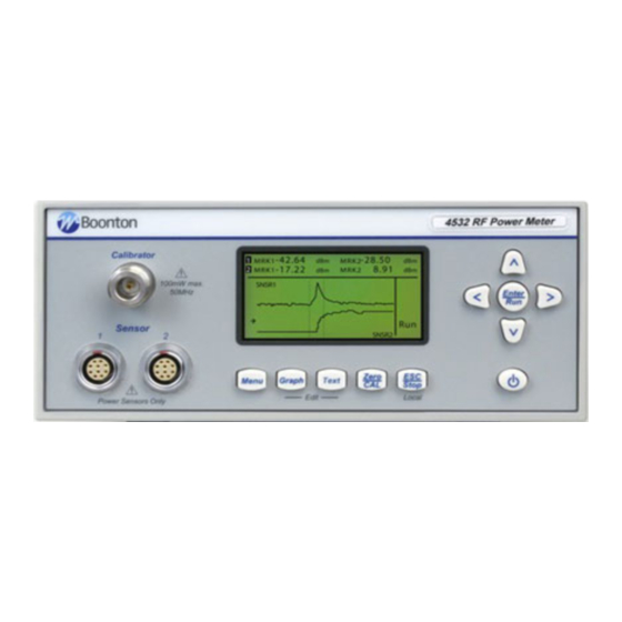
4530 SERIES
RF PEAK POWER METER
MODELS 4531 AND 4532
REV DATE 9/14/07
P/N 98405100A
BOONTON ELECTRONICS a WIRELESS TELECOM GROUP COMPANY
25 EASTMANS ROAD ■ PARSIPPANY, NEW JERSEY 07054-0465
boonton@boonton.com
■
TELEPHONE: (973) 386-9696
FAX: (973) 386-9191 ■ E-MAIL:
BOONTON ELECTRONICS a WIRELESS TELECOM GROUP COMPANY
1
Advertisement

Subscribe to Our Youtube Channel
Related Manuals for Boonton 4530 Series


Summary of Contents for Boonton 4530 Series
- Page 1 4530 SERIES RF PEAK POWER METER MODELS 4531 AND 4532 REV DATE 9/14/07 P/N 98405100A BOONTON ELECTRONICS a WIRELESS TELECOM GROUP COMPANY 25 EASTMANS ROAD ■ PARSIPPANY, NEW JERSEY 07054-0465 boonton@boonton.com ■ TELEPHONE: (973) 386-9696 FAX: (973) 386-9191 ■ E-MAIL:...
- Page 2 DIGITALY REMASTERED OUT OF PRINT- MANUAL SCAN ArtekMedia P.O. BOX 175 Welch, MN 55089-0175 Phone: 651-269-4265 www.artekmedia.com “High resolution scans of obsolete technical manuals” If you are looking for a quality scanned technical manual in PDF format please visit our WEB site at www.artekmedia.com or drop us an email at...
- Page 3 Section 3. 4530 Series Block Diagrams Section 4. 4530 Series Drawings Appendix Entering Data into Boonton Peak and CW Sensors © Copyright 2002-2007 by Boonton Electronics a Wireless Telecom Group Company, Parsippany, NJ, BOONTON ELECTRONICS a WIRELESS TELECOM GROUP COMPANY...
- Page 4 Note: The following procedures assume that the technician is familiar with the basic menu operation of the 4530 Series. To select menu items, press the MENU key twice to return to the top-level menu, and then use the up and down arrows to highlight the desired entry. Once highlighted, the right arrow or Enter key is used to select that entry.
- Page 5 Press ON/STBY key on front panel to return to “standby” mode, then after a few seconds press again to turn back “on” while observing the display. b. The display should show a start-up screen, the BOONTON logo, and then the main menu of the 4530.
-
Page 6: Sensor Detection
4. Monitor the sinewave with the oscilloscope, and adjust the function generator’s output level and offset so the signal has a peak amplitude of +/-4.7V (+/-100mV), and is symmetrical around 0V. BOONTON ELECTRONICS a WIRELESS TELECOM GROUP COMPANY Scans by ArtekMedia => 2009... - Page 7 Press the Right Arrow key until TimeSpn is highlighted in the Graph Mode Edit Menu, then press the Up key until the Time Span is set to 50usec. A square wave with sharp edge transitions should be displayed, although the falling edge may decay slowly near the bottom. BOONTON ELECTRONICS a WIRELESS TELECOM GROUP COMPANY...
- Page 8 Verify that now a serasoidal waveform (a highly filtered square wave with very slow rise and fall times) is displayed, which indicates that the sensor correctly switched to low bandwidth mode. BOONTON ELECTRONICS a WIRELESS TELECOM GROUP COMPANY Scans by ArtekMedia => 2009...
- Page 9 If the bottom line indicates “SelectExt”, then the internal calibrator is already selected. Set Main Menu > Calibratr > Int Level to 0.0dBm. Set Main Menu > Calibratr > Int Signal to “On”. BOONTON ELECTRONICS a WIRELESS TELECOM GROUP COMPANY...
- Page 10 Select “Auto Cal”. Press Enter. The 4530 will perform an automatic sensor power sweep calibration. Check for any error messages, then press the Text key. Channel 1 should display 0.000 dBm +-0.005dBm. BOONTON ELECTRONICS a WIRELESS TELECOM GROUP COMPANY Scans by ArtekMedia => 2009...
- Page 11 Press the Zero/CAL key. Select “Auto Cal”. Press Enter. The 4530 will perform an automatic sensor power sweep calibration. Check for any error messages, then press the Text key. Channel 2 should display 0.000 dBm +-0.005dBm. BOONTON ELECTRONICS a WIRELESS TELECOM GROUP COMPANY...
- Page 12 Note: The following procedures assume that the technician is familiar with the basic menu operation of the 4530 Series. To select menu items, press the MENU key twice to return to the top-level menu, and then use the up and down arrows to highlight the desired entry. Once highlighted, the right arrow or Enter key is used to select that entry.
- Page 13 Press ON/STBY key on front panel. c. The display should show a start-up screen, the BOONTON logo, and then the main menu of the 4530. Check that the fan is operating. If the menu is not shown, press the Menu key.
- Page 14 There is no need to perform RF alignment if all the above steps were completed successfully. BOONTON ELECTRONICS a WIRELESS TELECOM GROUP COMPANY Scans by ArtekMedia => 2009...
- Page 15 Remove the dummy load and connect an RF powermeter to the calibrator’s output. n. Verify that the calibrator output is between 20.5 and 21.4 dBm o. Send “OUTPUT:INTERNAL:SIGNAL OFF” to the UUT. p. Remove power from the 4530, and reinstall the cover. BOONTON ELECTRONICS a WIRELESS TELECOM GROUP COMPANY...
- Page 16 4 screws in the rear. Place the 4530 upside down on the bench and reconnect power. Turn on the instrument and allow several minutes warmup time. b. Set the Boonton Model 2510 DC RANGE CALIBRATOR Output to OFF and its Source Resistance to 1800 ohms.
- Page 17 Disconnect the 2510, remove power from the 4530, and reinstall the cover. 6) 50MHz Calibrator Calibration It is recommended that the 4530 be returned annually to Boonton Electronics for calibration. If that is not possible, the calibration accuracy of the 4530’s calibrator should be checked annually by performing the checkout at the end of this procedure, or by an equivalent method traceable to NIST standards.
-
Page 18: Test Setup
(Optional) Test Setup The switch should be wired so the output of the reference calibrator (Boonton Model 2520) is routed through an adapter to input “A” of the HP8761A Coaxial Switch, and the output of the UUT’s calibrator is routed through an identical adapter to input “B” of the switch. The reference powermeter’s sensor is connected to the switch common. - Page 19 If there is output, but it is not within this range, the calibrator may require RF alignment (see section above) or could be defective. Set the 2520’s RF output to 0.0dBm & “ON” BOONTON ELECTRONICS a WIRELESS TELECOM GROUP COMPANY...
- Page 20 On the Meas4530, zero the sensor as follows: Press the Zero/CAL key. Select the appropriate channel by pressing < or >. Select Zero Chan and press Enter, and wait for the zeroing process to complete. BOONTON ELECTRONICS a WIRELESS TELECOM GROUP COMPANY Scans by ArtekMedia => 2009...
-
Page 21: Calibration Verification
Wait at least one minute to allow the power sensor to cool from recent service at or above 0dBm. d. Set the 2520’s RF output to -60dBm & “OFF”, then [select 2520]. BOONTON ELECTRONICS a WIRELESS TELECOM GROUP COMPANY... - Page 22 Press the Text key twice. This displays a menu at the top of the display. Scroll left or right until Ld/ClrR is selected then press the DN arrow key. BOONTON ELECTRONICS a WIRELESS TELECOM GROUP COMPANY Scans by ArtekMedia => 2009...
- Page 23 5 dBm ________ ______ 0.030 10 dBm ________ ______ 0.030 15 dBm ________ ______ 0.030 20 dBm ________ ______ 0.030 q. Set the 2520’s RF output to -60dBm & “OFF” and disconnect the sensor. BOONTON ELECTRONICS a WIRELESS TELECOM GROUP COMPANY...
- Page 24 Section 3: 4530 Series Block Diagrams BOONTON ELECTRONICS a WIRELESS TELECOM GROUP COMPANY Scans by ArtekMedia => 2009...
- Page 25 Scans by Artekmedia => 2009 BOONTON ELECTRONICS a WIRELESS TELECOM GROUP COMPANY...
- Page 26 BOONTON ELECTRONICS a WIRELESS TELECOM GROUP COMPANY Scans by ArtekMedia => 2009...
- Page 27 Scans by Artekmedia => 2009 BOONTON ELECTRONICS a WIRELESS TELECOM GROUP COMPANY...
- Page 28 Section 4: 4530 Series Drawings BOONTON ELECTRONICS a WIRELESS TELECOM GROUP COMPANY Scans by ArtekMedia => 2009...
- Page 29 Scans by Artekmedia => 2009 BOONTON ELECTRONICS a WIRELESS TELECOM GROUP COMPANY...
- Page 30 ArtekMedia Digitally signed by ArtekMedia DN: cn=ArtekMedia, o=ArtekMedia.com, ou, email=manuals@ArtekMedia.com, c=US Date: 2011.10.03 11:32:59 -05'00' BOONTON ELECTRONICS a WIRELESS TELECOM GROUP COMPANY Scans by ArtekMedia => 2009...
- Page 31 Scans by Artekmedia => 2009 BOONTON ELECTRONICS a WIRELESS TELECOM GROUP COMPANY...
- Page 32 BOONTON ELECTRONICS a WIRELESS TELECOM GROUP COMPANY Scans by ArtekMedia => 2009...
- Page 33 Scans by Artekmedia => 2009 4530 Host Printed Wiring Assembly BOONTON ELECTRONICS a WIRELESS TELECOM GROUP COMPANY...
- Page 34 Data loading is accomplished through the IEEE-488 Bus and Model 4400, 4500, 4400A, 4500A, 4500B or 4530 series Power Meter. Data cannot be loaded into the sensor if it is not connected to a BOONTON Peak Power Meter. It is NOT possible to change one item in a data string without reloading the entire data string.
- Page 35 ASCII space (SP) followed by the data string. Commas separate the various elements of the data string. The mnemonic and data string cannot contain any embedded terminators (carriage return (CR) and line feed (LF)) before the end. BOONTON ELECTRONICS a WIRELESS TELECOM GROUP COMPANY...
- Page 36 RD-S-SLOW. Repeat the same process for TKSFAST/RD-S-FAST, or transmit the edited “slow” string to replace the “fast” data as well. BOONTON ELECTRONICS a WIRELESS TELECOM GROUP COMPANY Scans by ArtekMedia => 2009...
-
Page 37: Sensor Message
EFFECT OF CHANGES TO SENSOR DATA All BOONTON peak power meters will read and write data to the EEPROM of any peak sensor connected to an input. It is not necessary for the sensor in question to be auto-calibrated to perform the above data operations. - Page 38 OFF/ON cycle occurs. These models update immediately any changes made with the manual sensor data editor. This sensor data editor is available only from the front panel controls. snsr_cal.doc 20020911 BOONTON ELECTRONICS a WIRELESS TELECOM GROUP COMPANY Scans by ArtekMedia => 2009...
Need help?
Do you have a question about the 4530 Series and is the answer not in the manual?
Questions and answers