Table of Contents

Subscribe to Our Youtube Channel
Related Manuals for Boonton 9240 Series


Summary of Contents for Boonton 9240 Series
- Page 1 INSTRUCTION MANUAL 9240 SERIES RF VOLTMETER REV DATE 11/12/2015 MANUAL P/N 98406900B CD P/N 98406999B Wireless Telecom Group 25 EASTMANS ROAD, PARSIPPANY, NJ 07054 Telephone: 973-386-9696 Fax: 973-386-9191 Email: boonton@boonton.com Web: www.wtcom.com...
- Page 2 Boonton 9240 Series RF Voltmeter INSTRUCTION MANUAL, 9240 SERIES RF VOLTMETER Revision date 11/12/2015 © Copyright in 2005-2015, by BOONTON Electronics, a subsidiary of the Wireless Telecom Group, Inc. Parsippany, NJ, USA. All rights reserved. P/N 98406900B This manual covers instrument serial numbers: 11001 and higher.
- Page 3 Failure to comply with these precautions or with specific warnings elsewhere in this manual violates safety standards of design, manufacture, and intended use of the instrument. Boonton Electronics assumes no liability for the customer’s failure to comply with these requirements.
- Page 4 Boonton 9240 Series RF Voltmeter SAFETY SYMBOLS This safety requirement symbol (located on the rear panel) has been adopted by the International Electro-technical Commission, Document 66 (Central Office) 3, Paragraph 5.3, which directs that an instrument be so labeled if, for the correct use of the instrument, it is necessary to refer to the instruction manual.
-
Page 5: Table Of Contents
Boonton 9240 Series RF Voltmeter General Information ....................1-1 1.1 Organization ......................1-1 1.2 Description ......................1-2 1.3 Features ......................... 1-2 1.4 Accessories ......................1-5 Standard ....................... 1-5 Optional........................ 1-5 Optional........................ 1-6 ... - Page 6 5.3.5 Command Arguments and Queries ..............5-3 5.3.6 Semicolon Command Separators ..............5-3 5.3.7 Command Terminators .................. 5-3 5.3.8 9240 Series SCPI Implementation ..............5-3 5.4 Basic Measurement Information ................5-5 5.4.1 Service Request ....................5-5 ...
- Page 7 Boonton 9240 Series RF Voltmeter CALCulate:LIMit:LOWer[:POWer] ..............5-10 CALCulate:LIMit:UPPer[:POWer] ..............5-11 CALCulate:LIMit:LOWer:STATe ..............5-11 CALCulate:LIMit:UPPer:STATe ..............5-11 CALCulate:LIMit[:BOTH]:STATe ..............5-11 CALCulate:MATH:ARGA ................5-12 CALCulate:MATH:ARGB ................5-12 CALCulate:MATH:DATA? ................5-12 CALCulate:MATH:OPERator ................5-12 ...
- Page 8 Boonton 9240 Series RF Voltmeter OUTPut:RECorder:SOURce ................5-21 5.5.10 READ Queries ................... 5-22 READ:CW:VOLTage? ..................5-22 5.5.11 SENSe Subsystem ..................5-23 SENSe:FILTer:STATe ..................5-23 SENSe:FILTer:TIMe ..................5-23 5.5.12 STATus Commands ................... 5-24 STATus:DEVice:CONDition? ................5-24 ...
- Page 9 Boonton 9240 Series RF Voltmeter INSTrument:VERSion:FPGA? ................5-34 5.5.15 SCPI Command Summary ................. 5-35 5.5.16 9230 Emulation GPIB Commands............. 5-40 Maintenance ......................6-1 6.1 Safety ........................6-1 6.2 Cleaning ........................ 6-1 6.3 Inspection ......................6-1 ...
- Page 10 Boonton 9240 Series RF Voltmeter This page intentionally left blank. Contents...
-
Page 11: General Information
This instruction manual provides general information, installation and operating instructions for the Model 9240 Series of RF Voltmeters. The 9240 Series includes single channel Model 9241 and dual channel Model 9242. The terms 9240 and Model 9240 used throughout this manual refer to both configurations unless otherwise noted. -
Page 12: Description
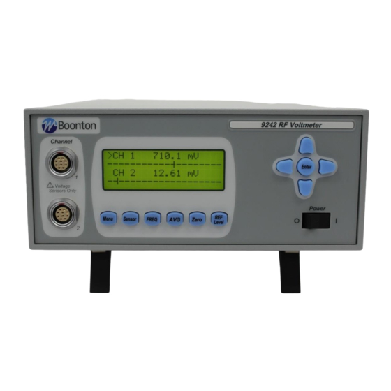
Simultaneous display of both channels is available in dual channel mode. A bar graph provides a display of the channel's measured value for nulling and peaking applications. Figure 1-1. 9240 Series RF Voltmeter General Information... - Page 13 Boonton 9240 Series RF Voltmeter Dual Independent Channels. When equipped with the optional second measurement channel, the instrument can display two CW signals simultaneously. Each channel is calibrated and all channel parameters are channel-independent. Selectable Ranging. Any of eight measurement ranges, or autoranging, can be selected during instrument setup.
- Page 14 Remote control programming is performed using industry-standard SCPI programming syntax. The 9230 emulation mode is provided for users that prefer back compatibility with legacy Boonton products such as the 9230 series line of RF Voltmeters.
-
Page 15: Accessories
Optional 9240 accessories that can be ordered from Boonton Electronics. A Sensor Data Adapter for each channel installed along with the AC power cord is supplied with the instrument. One or more Boonton 952000 series RF Voltage Probes is required and must be ordered separately. Probes are available with accessory kits and are sold separately. -
Page 16: Probes
Bulkhead Connector F/F, 41-2A (for connecting Model 41-2A cables end to end) 95201301A Accessory Case 98406900A Instruction Manual 9240 Series, English (Printed w/binder) Probes 952001 RF Probe - 10 kHz to 1.2 GHz 952016 Low Frequency RF Probe - 10 Hz to 100 MHz 1.5 Models, Options and Configurations... -
Page 17: Specifications
Boonton 9240 Series RF Voltmeter 1.6 Specifications Performance specifications for the 9240 Series are listed in Table 1-2. Table 1-2 9240 Series Performance Specifications (Specifications are subject to change without notice) VOLTAGE PROBE INPUTS Frequency Range: 10 Hz to 1.2 GHz... - Page 18 Boonton 9240 Series RF Voltmeter INPUT RESISTANCE VS. FREQUENCY, MODEL 952001B RF PROBE INPUT CAPACITANCE VS. INPUT VOLTAGE, MODEL 952001B RF PROBE Figure 1-2. Input Impedance General Information...
-
Page 19: Measurement System
Boonton 9240 Series RF Voltmeter Table 1-2 9240 Series Performance Specifications (continued) MEASUREMENT SYSTEM Voltage Probe Inputs: One or two measurement channels. Measurement Technique: 24 bit Sigma-delta A/D converter per channel. ACCURACY Basic Uncertainty : 3 mV – 10 V 1% rdg + 1 count 1 mV –... - Page 20 Boonton 9240 Series RF Voltmeter Table 1-2 9240 Series Performance Specifications (continued) Frequency Effect: Model 952016 Low Frequency Probe with Model 952002 50 BNC Adapter. Frequency dBV, dBmV, dBm, dBW 1 MHz (cal freq) 50 Hz - 20 MHz 1% rdg 0.09 dB...
-
Page 21: Physical And Environmental Characteristics
Boonton 9240 Series RF Voltmeter Table 1-2 9240 Series Performance Specifications (continued) EXTERNAL INTERFACES Remote Control: Complies with IEEE-488.1 and SCPI version 1993. GPIB: Implements AH1, SH1, T6, LE0, SR1, RL1, PP0, DC1, DT1, C0, and E1. RS232: Type-D connector, 9 pins. -
Page 22: Regulatory Characteristics
Boonton 9240 Series RF Voltmeter Table 1-2 9240 Series Performance Specifications (continued) REGULATORY CHARACTERISTICS CE Mark: Full compliance with the following European Union directives and standards: Safety: Low Voltage Directive 2006/95/EC IEC 61010 – 1 : 2001 (2 Edition); EN 61010 – 1 : 2001 (2... -
Page 23: Installation
2.1 Unpacking & Repacking The 9240 Series is shipped complete and is ready to use upon receipt. Figure 2-1 shows you the various pieces included in the packaging and the order in which they are loaded into the container. Actual details may vary from the illustration. -
Page 24: Power Requirements
2.2 Power Requirements The 9240 Series is equipped with a switching power supply that provides automatic operation from a 90 to 260 volt, 47 to 63 Hz, single-phase, AC power source. Maximum power consumption is 15W and 25VA. For metric fuse sizes, use the metric fuse kit supplied. -
Page 25: Preliminary Check
2. Attach the probe Data Adapter(s) to the front panel CHANNEL connector(s). Set the POWER switch to the ON (1) position. 4. Verify that "BOONTON ELECTRONICS, 9242 RF Voltmeter, Rev. XXXXXXXX" is momentarily displayed where XXXXXXXX represents the revision code. (Note: Model number 9241 display for single channel instruments.) While the sign-on screen is displayed the phrase “... - Page 26 Boonton 9240 Series RF Voltmeter 8. Use the <Down Arrow> key to move the "<" cursor to SWITCHES and press <ENTER>. Press each front panel key, avoiding <MENU> until last. Each key press will result in an identifying message; <MENU> will exit the test and return to the MENU.
-
Page 27: Getting Started
3. Getting Started This chapter will introduce the user to the 9240 Series. The chapter will identify objects on the front and rear panels, identify display organization, list the initial configuration of the instrument after reset, and provide practice exercises for front panel operation. - Page 28 Boonton 9240 Series RF Voltmeter Figure 3-1. Standard 9240 Series RF Voltmeter - Front Panel Table 3-1 Operating Controls, Indicators and Connections Reference # Front Rear Nomenclature Function Channel Inputs One or two Channel inputs are located on the front, or optionally on the rear panel of the instrument.
- Page 29 Boonton 9240 Series RF Voltmeter Table 3-1 Operating Controls, Indicators and Connections (continued) Reference # Front Rear Nomenclature Function ◄ and ► Keys In entry mode, pressing ◄advances the cursor to the left. In the measurement mode of operation pressing the ◄ key sets the Active channel to Linear measurement units (Volts, %).
- Page 30 Boonton 9240 Series RF Voltmeter Table 3-1 Operating Controls, Indicators and Connections (continued) Reference # Front Rear Nomenclature Function <REF Level> Key Often relative measurements are required especially when measuring system gains and losses. One key press of the Ref/Level key makes this easier and faster to perform.
- Page 31 Boonton 9240 Series RF Voltmeter Figure 3-2. 9240 Series - Rear Panel (Shown without optional rear panel connectors not installed) Getting Started...
-
Page 32: Operation
Boonton 9240 Series RF Voltmeter 3.3 Operation The Model 9240 can be configured for operation via the six switches on the front panel; <Menu> <Sensor> <FREQ> <AVG> <Zero> <REF Level> single key press operation) Pressing a key will bring the instrument to the next submenu. A flow chart of the instrument’s command structure is shown in figure 3-5. - Page 33 Boonton 9240 Series RF Voltmeter DUAL CHANNEL ± Δ ± Δ SINGLE CHANNEL ± Δ "=" 0 through 9 or a decimal point KEY: "=" (alarm mode) Ω (indicating power measurement relative ZØ) "=" CH1, CH2, CH1+2, CH1/2 "="...
- Page 34 Boonton 9240 Series RF Voltmeter Figure 3-5. Model 9240, Command Set Last Menu Operation. In keeping with minimum key stokes to perform a function repeatedly, the control program can remember the last menu the user was at prior to returning to the measurement display. In doing this submenu functions can be quickly selected and parameters changed getting the user back to the measurement display faster.
-
Page 35: Menu Key
Boonton 9240 Series RF Voltmeter 3.3.1 Menu Key. The instrument's, CHANNELS, SETUP, REPORT and DIAGNOSTIC functions are accessed when the <Menu> key is pressed (see Figure 3-6). Using the up/down arrow keys, the cursor can be positioned to select from the four submenus. - Page 36 Boonton 9240 Series RF Voltmeter Table 3-2 CHANNEL MENU Functions Function Description Parameters Defaults Returns the instrument to the previous menu. UNITS Units used for measurement dBm, WATTS display. Display resolution X.X, X.XX, X.XXX dBm or/ X.XX XXX, XXXX, XXXXX Watts...
- Page 37 Boonton 9240 Series RF Voltmeter > Figure 3-8. Setup Menu Display Table 3-3 SETUP MENU Functions Function Description Parameters Defaults Returns the instrument to the previous menu. RECALL Recalls one of ten user DEFAULT, 1-10, DEFAULT defined instrument SANITIZE configurations or the factory setup.
- Page 38 Boonton 9240 Series RF Voltmeter IEEE Menu. The IEEE submenu is used to configure the Model 9240 for communications over the GPIB. An example of the menu is shown in Figure 3-9 and the description of the commands, parameters and factory defaults is given in Table 3-4.
- Page 39 Boonton 9240 Series RF Voltmeter RS232 Menu. The RS232 menu is used to configure the Model 9240 for serial communications over the RS-232 bus. An example of the submenu is shown in Figure 3-10 and an explanation of the commands, parameters and factory defaults is given in Table 3-5.
- Page 40 Boonton 9240 Series RF Voltmeter REPORT Display. The REPORT menu item displays the versions of the firmware and FPGA image installed in the instrument. The SCPI specification compliance version is also displayed in this report. This display is for informational purposes only and does not support any editing of the data.
-
Page 41: Sensor Key
Boonton 9240 Series RF Voltmeter 3.3.2 Sensor Key. Pressing the <Sensor> key brings the instrument to the Sensor menu and facilitates viewing and editing of the voltage probe’s parameters. An access code is required to enter the editing mode (refer to Figure 3-14). A sample display of the Sensor menu is shown in Figure 3-13. - Page 42 Boonton 9240 Series RF Voltmeter > Figure 3-14. Sensor Edit Data Menu Display The parameter list will show TBLn (where n = 1, 2, 3, 4) when a serial number has not been entered for the corresponding internal table. For example, TBL3 will be displayed if the serial number has not been previously entered for internal table 3. In addition, the parameter list will show ADPTn (where n = 1, 2) if a serial number has not been entered for the table contained within the sensor data adapter.
-
Page 43: Freq Key
3.3.3 FREQ Key. This key provides for the setting of the measured frequency so that frequency calibration factors can be applied to the measurement. However, the Boonton series of voltage probes do NOT provide this functionality hence making this a null function. -
Page 44: Zero Key (Single Key Press Operation)
Boonton 9240 Series RF Voltmeter > Figure 3-17. Averaging Time Display 3.3.5 Zero Key (single key press operation). Zeroing should be performed when the unit is first warmed-up, a sensor has been changed or the instrument has drifted a significant amount with respect to the signal level being measured. For large signals (measurements taken on range 4, 5, 6 or 7), this may be done once every several hours. - Page 45 Boonton 9240 Series RF Voltmeter Press the <REF Level> key to enter a value or to use the current channel measurement for the reference level. The measurement units will automatically change to dBr for logrythmic units or % for linear units for subsequent measurements.
- Page 46 Boonton 9240 Series RF Voltmeter This page intentionally left blank. 3-20 Getting Started...
-
Page 47: Operation
Boonton 9240 Series RF Voltmeter 4. Operation This section provides detailed background information on various aspects of operation of the Model 9240. It is assumed that the reader is familiar with the basic operating procedures covered in Section 3. This section covers the following topics: Voltmeter Probe calibration, Zeroing, Filtering, Noise, Dynamic range, Measurement time, Chart recorder operation and Waveform sensitivity. -
Page 48: Connection Recommendations
Boonton 9240 Series RF Voltmeter The terminated Model 952009 RF Probe should not be subjected to continuous overload of more than 4 volts (DC + RMS AC) in order to avoid excessive heating of the terminating resistor. Exceeding these limits may result in permanent damage. -
Page 49: Temperature Effects
Boonton 9240 Series RF Voltmeter Temperature Effects 1. The accuracy specifications for the instrument apply over a temperature range of 0C to 50C. Outside these limits, operation of the instrument is possible, but appreciable inaccuracies can be expected; however, no permanent change in probe characteristics will result from any reasonably high or low temperature exposure. -
Page 50: Rf Power Measurements
Boonton 9240 Series RF Voltmeter Figure 3-4. Correction Curves for Models 952003 and 952007 Type N tee Adapters. 4.11 RF Power Measurements The Z function in the CHANNELS sub-menu enables the user to set a characteristic impedance to be used for power calculations. -
Page 51: Remote Operation
Boonton 9240 Series RF Voltmeter 5. Remote Operation 5.1 GPIB Configuration The 9240 GPIB interface is configured using the Menu > SETUP > IEEE menu. The primary listen/talk address (MLTA) can be set to any value from 1 to 30 inclusive. The value assigned must be unique to each GPIB device. Secondary address is not implemented. -
Page 52: Scpi Language
5.3.3 Subsystem Numeric Suffixes Certain subsystems, such as the SENSe or CALCulate subsystems in the 9240 Series, often exist as more than one instance (often called a “channel” in an instrument). In this case, an optional numeric suffix may be used to define the channel. If this... -
Page 53: Colon Keyword Separators
Boonton 9240 Series RF Voltmeter suffix is not present, the default channel is assumed. For example, SENSe or SENSe1 defines operation affecting the instrument’s “Channel 1” measurement path, while SENSe2 commands will apply to channel 2. 5.3.4 Colon Keyword Separators The colon (“:”) character is used similar to the way a slash or backslash is used in a filesystem. - Page 54 Boonton 9240 Series RF Voltmeter to zero the measurement channel. Channel dependent commands end with a number to indicate the desired channel as follows: Examples: :CALCulate:STATe ON Turn on measurement channel 1 (default channel number) :CALCulate1:STATe ON Turn on measurement channel 1 (specified channel number)
-
Page 55: Basic Measurement Information
Boonton 9240 Series RF Voltmeter 5.4 Basic Measurement Information The easiest way to obtain a reading is by use of the MEASure command. This command initiates one complete measurement sequence which includes a default configuration. Examples are: MEAS1:POWER? To return the average power of channel 1, or MEAS1:VOLTAGE? To return the average voltage of channel 1. -
Page 56: Scpi Command Reference
Boonton 9240 Series RF Voltmeter 5.5 SCPI Command Reference This section contains a list of all SCPI remote commands accepted by the 9240 Series. The list is grouped by SCPI subsystem or IEEE488.2 function, and includes a detailed description of each command. -
Page 57: Esr
Boonton 9240 Series RF Voltmeter *ESR? Description: Return the current value of the Standard Event Status Register, then clear the register. This register has bits assigned to a number of possible events or conditions of the instrument. When the event occurs, the corresponding bit is latched. -
Page 58: Opt
Boonton 9240 Series RF Voltmeter *OPT? Description: Return the status of Channel 1 and Channel 2 followed by a list of installed options. Syntax: *OPT? Returns: <f1, f2, f3, f4, opt1, opt2, …> : f1 – Chan 1 installed?, f2 – Chan1 sensor present?, f3 – Chan 2 installed?, f4 –... -
Page 59: Stb
Boonton 9240 Series RF Voltmeter *STB? Description: Return the current value of the Status Byte register. This register has bits assigned to a number of possible events or conditions of the instrument. The register value may be read using this command, or may be used to generate a service request (SRQ) over the GPIB when certain conditions exist. -
Page 60: Calculate Subsystem
Boonton 9240 Series RF Voltmeter 5.5.2 CALCulate Subsystem The CALCulate group of the command subsystem is used to configure post acquisition data processing. Functions in the CALCulate subsystem are used to configure the measurement mode and control which portions of the acquired measurement data is used and how it is processed to yield a finished measurement. -
Page 61: Calculate:limit:upper[:Power]
Boonton 9240 Series RF Voltmeter CALCulate:LIMit:UPPer[:POWer] Description: Set or return the upper limit power level for the selected channel. This limit is used for level alarms. When the measured average power is above the upper limit, an up arrow ▲ will appear on the display to the left of the measured value and flag bits are set in the alarm register which may be accessed using CALCulate:LIMit:FAIL? query and CALCulate:LIMit:CLEAR commands. -
Page 62: Calculate:math:arga
Boonton 9240 Series RF Voltmeter CALCulate:MATH:ARGA Description: Set or return the first argument to be used for channel math operations. Syntax: CALCulate:MATH:ARGA <character data> Argument: <character data> = { CH1, CH2 } CALCulate:MATH:ARGB Description: Set or return the second argument to be used for channel math operations. -
Page 63: Calculate:reference:collect
Boonton 9240 Series RF Voltmeter CALCulate:REFerence:COLLect Description: For the selected channel, make the current power the reference level for ratiometric measurements, replacing the previous reference level. CALCulate[1|2]:REFerence:COLLect Syntax: Argument: None CALCulate:REFerence:DATA Description: For the selected channel, set the power level specified by the argument as the reference level for ratiometric measurements, replacing the previous reference level. -
Page 64: Calibration Subsystem
Boonton 9240 Series RF Voltmeter 5.5.3 CALibration Subsystem The CALibration group of commands is used to control automatic zero offset to the RF Voltage probe and the channel to which it is connected. Zero offset adjustment can be performed at any time if no RF signal is applied to the probe. -
Page 65: Display Subsystem
Boonton 9240 Series RF Voltmeter 5.5.4 DISPlay Subsystem The DISPlay group of commands is used to control the selection and presentation of measurements. DISPlay:ACTive[?] Description: Set or return the active channel for talk commands. Syntax: DISPlay:ACTive <numeric value> Argument: <numeric value> = 1 to 2... -
Page 66: Display:label:texta
Boonton 9240 Series RF Voltmeter DISPlay:LABel:TEXTA Description: Displays a text message of up to 20 characters in the first label field when Display Label Mode is enabled. Syntax: DISPlay:LABel:TEXTA <alphanumeric value> Argument: <alphanumeric value> = A to Z, a to z, 0 to 9, ! @ # $ % ^ & * ( ) _ - + = { } [ ] ? / < > : . -
Page 67: Fetch Queries
Boonton 9240 Series RF Voltmeter 5.5.5 FETCh Queries The FETCh? group of queries is used to return specific measurement data from a measurement cycle that has been INITiated and is complete or free-running. FETCh? performs the data output portion of the measurement. FETCh? does not start a new measurement, so a series of FETCh? queries may be used to return more than one set of processed measurements from a complete set of acquired data. -
Page 68: Initiate And Abort Commands
Boonton 9240 Series RF Voltmeter 5.5.6 INITiate and ABORt Commands The purpose of the INITiate group of commands is to start and control the process of data acquisition once a measurement has been configured. Depending on settings, the 9240 RF Voltmeter may be commanded to begin either a single measurement (INITiate:CONTinuous OFF) which stops when complete, or enter a “free-run”... -
Page 69: Measure Queries
Boonton 9240 Series RF Voltmeter 5.5.7 MEASure Queries The MEASure group of commands is used to acquire data using a set of high level instructions. They are structured to allow the user to trade off fine control of the measurement process for easy operability. MEASure? provides a complete capability where the voltmeter is configured, a measurement taken, and results returned in one operation. -
Page 70: Memory Subsystem
Boonton 9240 Series RF Voltmeter 5.5.8 MEMory Subsystem The MEMory group of commands is used to save and recall instrument operating configurations. Up to ten configurations may be saved. MEMory:SNSR:CWRG? Description: Return sensor AC cal data. Syntax: MEMory:SNSR[1|2]:CWRG? Argument: None, query only. -
Page 71: Output Subsystem
Boonton 9240 Series RF Voltmeter 5.5.9 OUTPut Subsystem The OUTPut group of commands is used to control various outputs of the 9240. These outputs include the Recorder Output. OUTPut commands for the Recorder Output include setting the DC output to the MAXimum or MINimum level or can be forced to any level in between. -
Page 72: Read Queries
Boonton 9240 Series RF Voltmeter 5.5.10 READ Queries The purpose of the READ? group of queries is to initiate a measurement cycle, acquire data, and return specific measurement data. READ? performs the initiation, data acquisition, postprocessing, and data output portions of the measurement. READ? is equivalent to ABORting any operation in progress, INITiating a new measurement, then FETChing the data when it is ready. -
Page 73: Sense Subsystem
SENSe1 and SENSe2 represent the instrument’s SENSOR 1 and SENSOR 2 signal paths, respectively. The SENSe commands generally DO NOT affect the data processing and display portion of the measurement (see the CALCulate subsystem, Section 5.5.2). Note that SENSe2 commands will generate an error if used with a single channel 9240 Series instrument. -
Page 74: Status Commands
Boonton 9240 Series RF Voltmeter 5.5.12 STATus Commands The STATus command subsystem enables you to control the SCPI defined status reporting structures. The user may examine the status or control status reporting of the voltmeter by accessing the Device, Operation and Questionable status groups... -
Page 75: Status:device:event
Boonton 9240 Series RF Voltmeter STATus:DEVice:EVENt? Description: Returns the current contents of the Device Event register then resets the register value to 0. The Device Event register contains the latched events from the Device Condition register as specified by the Device status group’s positive and negative transition filters. -
Page 76: Status:operation:condition
Boonton 9240 Series RF Voltmeter STATus:OPERation:CONDition? Description: Return the current value of the Operation Condition register. The following table shows the bit assignments in the register. These bits are updated by the instrument in real time, and can change in response to changes in the instrument’s operating condition. -
Page 77: Status:operation:ntransition
Boonton 9240 Series RF Voltmeter STATus:OPERation:NTRansition Description: Set or return the value of the negative transition filter bitmask for the Operation status group. Setting a bit in the negative transition filter causes a 1 to 0 (negative) transition in the corresponding bit of the Operation Condition register to cause a 1 to be written in the associated bit of the Operation Event register. -
Page 78: Status:questionable:condition
Boonton 9240 Series RF Voltmeter STATus:QUEStionable:CONDition? Description: Return the current value of the Questionable Condition register. The following table shows the bit assignments in the register. These bits are updated by the instrument in real time, and can change in response to changes in the instrument’s operating condition. -
Page 79: Status:questionable:ntransition
Boonton 9240 Series RF Voltmeter STATus:QUEStionable:NTRansition Description: Set or return the value of the negative transition filter bit mask for the Questionable status group. Setting a bit in the negative transition filter causes a 1 to 0 (negative) transition in the corresponding bit of the Questionable Condition register to cause a 1 to be written in the associated bit of the Questionable Event register. -
Page 80: Status:questionable:calibration:enable
Boonton 9240 Series RF Voltmeter STATus:QUEStionable:CALibration:ENABle Description: Sets or returns the Questionable Calibration Enable register, which contains the bit mask that defines which true conditions in the Questionable Calibration Event register will be reported in the Questionable Calibration Summary bit of the Questionable Condition register. If any bit is 1 in the Questionable Calibration Enable register and its corresponding Questionable Calibration Event bit is true, the Questionable Calibration summary bit will be set. -
Page 81: System Subsystem
Boonton 9240 Series RF Voltmeter 5.5.13 SYSTem Subsystem The SYSTem group of commands is used to control system-level functions not directly related to instrument measurement performance. SYSTem commands are used to return error codes or messages from the voltmeter error queue, control hardware features and configure communication parameters for the GPIB. -
Page 82: System:communicate:gpib:talk
Boonton 9240 Series RF Voltmeter SYSTem:COMMunicate:GPIB:TALK Description: Set or return the GPIB Talk end-of-string terminator . Syntax: SYSTem:COMMunicate:GPIB:TALK <character data> Argument: <character data> = {LF, CR, CRLF, EOIONLY} SYSTem:COMMunicate:SERial:BAUD Description: Set or return the RS232 baud rate. SYSTem:COMMunicate:SERial:BAUD <numeric value>... -
Page 83: System:error[:Next]
Boonton 9240 Series RF Voltmeter SYSTem:ERRor[:NEXT]? Description: Returns the next queued error code number followed by a quoted ASCII text string describing the error. Note that errors are stored in a “first-in-first-out” queue, so if more than one error has occurred, repeating this command will report the errors in the sequence they happened. -
Page 84: Instrument:version Commands
Boonton 9240 Series RF Voltmeter 5.5.14 INSTrument:VERSion Commands INSTrument:VERSion group of commands is used to query the firmware and FPGA revision codes. The firmware code follows a “YYYYMMDD” format. The FPGA revision format has a major and minor representation in the form of “MM.mm”... -
Page 85: Scpi Command Summary
Boonton 9240 Series RF Voltmeter 5.5.15 SCPI Command Summary Table 5-1. SCPI COMMAND SUMMARY *CLS Clear Status Command *ESE Set/get Standard Event Status Enable *ESR? Standard Event Status Register Query *IDN Identification Query *OPC Operation Complete Command *OPC? Operation Complete Query... - Page 86 Boonton 9240 Series RF Voltmeter Table 5-1. SCPI COMMAND SUMMARY (continued) CALCulate:MATH:ARGB Set or return the second argument to be used for channel math operations. CALCulate:MATH:DATA? Returns the channel math result. CALCulate:MATH:OPERator Set or return the channel math operator. CALCulate:MODE Set/return remote measurement mode <character data>...
- Page 87 Boonton 9240 Series RF Voltmeter Table 5-1. SCPI COMMAND SUMMARY (continued) DISPlay:Label:TEXTD Displays a text message in the fourth label field. <alphanumeric value> = A to Z, a to z, 0 to 9 ! @ # $ % ^ & * ( ) _ - + = { } [ ] ? / <...
- Page 88 Boonton 9240 Series RF Voltmeter 5-1. SCPI COMMAND SUMMARY (continued) STATus:DEVice:NTRansition Set/return the Negative Transition filter STATus:DEVice:PTRansition Set/return the Positive Transition filter STATus:OPERation:CONDition? Return value of Operation Condition Register STATus:OPERation:ENABle Set/return value of Operation Enable Mask STATus:OPERation:EVENt? Return value of Operation Event Register...
- Page 89 Boonton 9240 Series RF Voltmeter Table 5-1. SCPI COMMAND SUMMARY (continued) SYSTem:COMMunicate:SERial:BAUD Set/return the RS232 baud rate. <numeric value> = 300, 600, 1200, 2400, 4800, 9600, 19200, 38400, 57600, 115200 SYSTem:COMMunicate:SERial:BITS Set/return the RS232 serial Data Bits. <numeric value> = 7,8 SYSTem:COMMunicate:SERial:PARity Set/return the RS232 Parity.
-
Page 90: 9230 Emulation Gpib Commands
Boonton 9240 Series RF Voltmeter 5.5.16 9230 Emulation GPIB Commands Table 5-2. 4230 EMULATION GPIB COMMANDS Code Description Comment Measure A-B Measure A/B Measure B - A Measure B/A 4230A Native mode Channel select 1 - 2 Clear dBm select... - Page 91 Boonton 9240 Series RF Voltmeter Table 5-2. 4230 EMULATION GPIB COMMANDS (continued) Code Description Comments Recall instrument configuration 1 - 10 Resolution 1 - 3 Recorder normal Range select 0 - 6 Recorder top SCPI Set remote programming language to SCPI...
- Page 92 Boonton 9240 Series RF Voltmeter This page intentionally left blank. 5-42 Remote Operation...
-
Page 93: Maintenance
Boonton Electronics for service. 6.4 Firmware Upgrade Operating Firmware has been loaded into the 9240 Series instrument at the factory. The Firmware will be updated from time to time to correct errors and add new features. Users can upgrade their firmware by downloading a special Firmware Upgrade file from the Boonton Electronics webpage, www.boonton.com. -
Page 94: Firmware Upgrade Instructions
Boonton 9240 Series RF Power Meter 6.5 Firmware Upgrade Instructions The Firmware Update file is a text file in S-record format. Any utility that can send a text file over Requirements the GPIB interface could be used, however, it is recommended that National Instruments VISA Interactive Controller (VIC) utility that is available with installation of their VISA (Virtual Instrument Software Architecture) product be used as this has been tried and tested. - Page 95 Boonton 9240 Series RF Power Meter 7. During this time the 9240 will display "FIRMWARE DOWNLOAD". The download takes approximate 45 seconds to completely transfer. 8. When the End-Of-File is reached the message “PROGRAMMING FLASH” will be displayed on the 9240. Flash programming takes approximately 5 seconds to complete.
- Page 96 Boonton 9240 Series RF Power Meter This page intentionally left blank. Maintenance...
-
Page 97: Appendix A Scpi Error Messages
Boonton 9240 Series RF Power Meter 7. Appendix A SCPI Error Messages 7.1 SCPI Error Messages MESSAGE DESCRIPTION “No Error” -100 "Command Error" -101 “SubCmd not found” -102 "Syntax error" -103 “Too many qry” -108 "Parameter not allowed" -109 "Missing parameter"... - Page 98 Boonton 9240 Series RF Power Meter MESSAGE DESCRIPTION -245 "Sensor Disconnected." -246 “Sensor voltage error” -248 "Keyboard error" -249 "FPGA download err" -263 “MFS Init” -264 “Flash init” -266 “Mem restore” -280 “Program error” -295 "Command not in language." -296 "Data out of range, set to limit."...
-
Page 99: Appendix B Warranty & Repair
The probe must be returned in its original packing container. If the original container is not available, Boonton Electronics will ship a replacement container and you will be billed for the container cost and shipping charges. If a new sensor is ordered, note that it does not include a sensor cable - this item must be ordered separately. - Page 100 THE FOREGOING WARRANTIES ARE IN LIEU OF ALL OTHER WARRANTIES, EXPRESS OR IMPLIED, INCLUD-ING, BUT NOT LIMITED TO, THE IMPLIED WARRANTIES OF MERCHANTABILITY AND FITNESS FOR A PAR-TICULAR PURPOSE. Boonton will not be liable for any incidental damages or for any consequential damages, as defined in Section 2-715 of the Uniform Commercial Code, in connection with products covered by the foregoing warranties.
Need help?
Do you have a question about the 9240 Series and is the answer not in the manual?
Questions and answers