Table of Contents
Advertisement
Quick Links
Advertisement
Table of Contents

Related Manuals for Gates CORTEX


Summary of Contents for Gates CORTEX
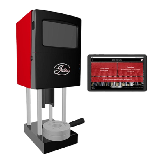
- Page 1 GATES GC20 WITH ™ ® GATES CORTEX INTELLIGENCE ™ ® OPERATING AND SAFETY MANUAL...
- Page 2 USE THIS MACHINE ONLY IF YOU: 1. Complete your TRAINING with this Gates crimper and assemblies. 2. Follow current GATES OPERATING INSTRUCTIONS for the Gates GC20 Cortex. 3. Use only NEW (UNUSED GATES) hoses and fittings. 4. Wear SAFETY GLASSES.
-
Page 3: Table Of Contents
TABLE OF CONTENTS Gates GC20 Cortex Specifications........................1 Gates GC20 Cortex..........................Setup..........................4 Install the Crimper..........................Set up the Tablet........................... Calibrate the Crimper......................... Tablet Menu Map......................19 Pull-Down Menu..........................People and Account Menu........................ Main Screen............................Tablet Operation......................23 Administrator and Operator Accounts.................... - Page 4 Gates GC20 Cortex Converting to 230V....................... 60 General Instructions for Converting to 230V................... Retrofitting a Crimper....................61 Remove Old Components......................... Add New Components to the Crimper....................Troubleshooting......................80 GATES.COM Table of ConTenTs...
-
Page 5: Specifications
Production Rate: 50 assemblies per hour (1/2" I.D. 2-wire straight thread assemblies) * Gates GC20 Cortex can also be wired for 230 volts. To do this, order G20 Cortex 230V converter kit (Prod. No. 7482-0047, Part No. 70435). ELECTRO POWER PUMP Prod. -
Page 6: Gates Gc20 Cortex
Gates GC20 Cortex GATES GC20 CORTEx DIE SETS ARE AVAILABLE FOR CRIMPING HYDRAULIC AND INDUSTRIAL HOSE FROM 3/16" THROUGH 1-1/4" I.D. PRODUCT PART DESCRIPTION NOTES NUMBER NUMBER Die Set 720S 7482-1401 78254 For crimping 4GLX — uses 20- and 30-series dies GLX couplings leave a “bubble”... - Page 7 Gates GC20 Cortex PRODUCT PART DESCRIPTION NOTES NUMBER NUMBER Die Set 73537 (LG) 7482-1427 78766 For crimping Lifeguard Die Set 73638 (LG) 7482-1428 78767 For crimping Lifeguard NOTE: Do not use the 720, 735, 737, or 739 die sets with the notched die cone (sold separately).
-
Page 8: Setup
SETUP Gates GC20 Cortex There are three main steps to setting up the Gates GC20 Cortex: ■ Install the crimper on a workbench, connect the pump, and power up. ■ Set up the tablet. (page 8) ■ Calibrate the crimper. (page 12) INSTALL THE CRIMPER 1. - Page 9 Gates GC20 Cortex Figure 2: Drill three holes in the workbench (plan view) 4. When you have a secured the crimper to the workbench, connect the hoses between crimper and pump, as in Figure 3, Figure 4, and Figure 5.
- Page 10 Gates GC20 Cortex High-Pressure Hose with 20LG4K Sleeve Fluid return hose Fluid return hose Figure 4: Hose connections 6MxT Hose with 90-Degree coupling Figure 5: 6MxT hose connected to return port on pump GATES.COM seTup...
- Page 11 7. Plug the cord of the crimper into a 115VAC/15 amp outlet. This immediately provides power to the crimper electronics. Figure 6: Gates GC20 Cortex 8. Remove plug from the top of the pump reservoir and replace it with the breather cap provided.
-
Page 12: Set Up The Tablet
Bluetooth Figure 7: Bluetooth and WiFi symbols on the tablet 3. Find the pre-installed application named GATES CORTEX CRIMP in the list of applications on the tablet, and tap it to start it. The Welcome screen appears on the tablet (Figure 8). - Page 13 4. On the faceplate of the crimper, the white “WiFi” symbol illuminates, showing that crimper is connected to WiFi (Figure 9). The Bluetooth and WiFi symbols on the faceplate only illuminate when the Gates application is running and when the tablet and the crimper are connected.
- Page 14 PRESS HERE TO CONTINUE. Wait for the validation confirmation before continuing. 8. The Gates GC20 Cortex gives you an opportunity to set up an Administrator account and Operator accounts if you want them. You can skip setting up Admin/Operator accounts and do this later or not at all, or you can set up an Administrator account now.
- Page 15 Gates GC20 Cortex For more information about setting up Administrator and Operator accounts, how they affect your use of the crimper, and about operating the tablet generally, see “Tablet Operation” on page i. 9. When you have set up Administrator and Operator accounts (or when you have skipped setting them up), the tablet confirms that setup is complete, as in Figure 11.
-
Page 16: Calibrate The Crimper
Gates GC20 Cortex CALIBRATE THE CRIMPER Once tablet setup and registration are complete, you can perform a Setup Calibration of the crimper. CAUTION: Always wear safety glasses and KEEP HANDS AWAY FROM MOVING PARTS. Depending on whether you have set up Admin and Operator accounts, you may need to log in with your PIN. - Page 17 Gates GC20 Cortex Pulldown menu Figure 13: Application Home screen 3. From the pulldown menu, choose APPLICATION SETTINGS. The application opens the Application Settings screen. Figure 14: Application Settings screen 4. Tap CALIBRATION SETTINGS. The application opens the Calibration Settings screen (Figure 15).
- Page 18 Gates GC20 Cortex Figure 15: Calibration Settings screen 5. Tap PERFORM INITIAL SETUP CALIBRATION. The tablet guides you step-by- step through the initial calibration. There are two steps: Step 1 (Figure 16) requires no additional tools. You will be instructed on a series of steps to purge the air from all lines by cycling the crimper five times.
- Page 19 Gates GC20 Cortex Figure 17: Calibration cycle one 7. Press and hold the red PRESS & HOLD TO CYCLE button until the cycle is completed and the button turns to green. The cycle count appears to the right of the dot (Figure 18). Perform this cycle five times, as directed by the software.
- Page 20 Gates GC20 Cortex 8. The last cycle retracts the pusher cup and asks you to wait 60 seconds, (Figure 19). Figure 19: Last of five cycles; ram retracting 9. Step 2 lists its requirements on screen, which include a specific coupling and a specific die set, but no hose.
- Page 21 Gates GC20 Cortex 10. Press and hold the red PRESS & HOLD TO CYCLE button. The Gates GC20 Cortex crimps the coupling. 11. After the crimp, the application displays a screen where you can enter the measured diameter of the coupling you have just crimped (shown in Figure 21 on page 17).
- Page 22 Gates GC20 Cortex Figure 22: Crimp diameter outside of tolerance; re-run the calibration crimp 13. Tap PROCEED and re-do the Calibration crimp. The crimper recalculates its stroke each time you report a measured crimp diameter that is outside of tolerance.
-
Page 23: Tablet Menu Map
TABLET MENU MAP Gates GC20 Cortex These tables show you what the various menu selections do and where they lead you. PULL-DOWN MENU PULL-DOWN CHOICE… SHOWS… WHERE YOU FIND… Closes the menu. Goes to x – CLOSE Home Page HOME Home Page Training Videos and PDFs;... - Page 24 Edit an Existing Maintenance Action crimper Calculator Unit Converter REFERENCE TOOLS Remote support (allows support to TeamViewer operate the tablet and crimper) Key Gates phone numbers and CONTACT US addresses + link to Gates.com GATES.COM TableT Menu Map...
-
Page 25: People And Account Menu
Gates GC20 Cortex PEOPLE AND ACCOUNT MENU ■ Create Administrator Account ■ Create an Operator Account (once you have created an Administrator Account) For more information about creating Administrator and Operator accounts, see “Tablet Operation” on page 10. GATES.COM TableT Menu Map... -
Page 26: Main Screen
Gates GC20 Cortex MAIN SCREEN MAIN SCREEN STEP STEP STEP STEP BUTTON Select Hose Type Select Hose Size Select Coupling for Press and Hold to (Possibly Pressure) Stem ONE Crimp End 1 Select Coupling for Press and Hold to CRIMP HOSE... -
Page 27: Tablet Operation
“Setup” on page 4. ADMINISTRATOR AND OPERATOR ACCOUNTS You can set up the tablet and the Gates GC20 Cortex with Administrator and Operator accounts during initial setup or at any time after setting up. Setting up Administrator and Operator accounts is not required to use the tablet or crimper. -
Page 28: To Create An Administrator Account
Figure 25: Create Administrator Account 2. Fill in the account information including the PIN at the bottom (you may choose any PIN; Gates suggests not making all four the same number), and then tap SAVE. The application displays the Account Settings screen (Figure 26). -
Page 29: To Add An Operator
Gates GC20 Cortex Figure 26: Account Settings screen, showing the new Administrator account TO ADD AN OPERATOR 1. Log in using your Administrator PIN (Operators with Administrator access can log in for this task, too) OR if you’re already logged in, choose ACCOUNT SETTINGS from the People and Account menu, as shown in (Figure 27). - Page 30 Gates GC20 Cortex Figure 28: Account Settings screen 2. Tap ADD AN OPERATOR. The application displays the Create New Operator Account screen, (Figure 29). Figure 29: Create a New Operator Account 3. Fill in the fields of the screen, and then tap SAVE. The application displays the Account Settings screen, showing the new Operator account (Figure 30).
-
Page 31: To Give An Operator Account Administrator Access
Gates GC20 Cortex Figure 30: New operator is added TO GIVE AN OPERATOR ACCOUNT ADMINISTRATOR ACCESS 1. On the Account Settings screen, move the ADMIN ACCESS slider right for an Operator until it changes color (Figure 31). Slide it back left to remove ADMIN ACCESS. -
Page 32: View Video Tutorials, Catalogs, And Images
The application offers quick links to the tablet’s on-board calculator, to a unit converter application, and to TeamViewer, an application that allows the support experts at Gates to control your tablet remotely if necessary. From time to time, Gates may make additional utilities and support applications available to the tablet. - Page 33 Gates GC20 Cortex Figure 33: Reference Tools screen GATES.COM TableT operaTion...
-
Page 34: Hose Preparation
HOSE PREPARATION Gates GC20 Cortex CAUTION: You must use a new hose and end fittings (stem/ferrule) when building a hose assembly. Re-using any component will seriously affect performance and could result in serious injury or property damage. TWO-PIECE COUPLINGS 1. Cut hose to desired length. - Page 35 Gates GC20 Cortex Figure 35: Hose pushed onto stem up to stem shoulder 6. Push ferrule so that it rests against hex of stem, as in Figure 36. Hose and coupling are now ready for crimping. Figure 36: Push ferrule to hex of stem GATES.COM...
-
Page 36: Megacrimp ® Pre-Assembled Couplings
Gates GC20 Cortex MEGACRIMP PRE-ASSEMBLED COUPLINGS ® 1. Cut hose to desired length. 2. Obtain the correct stem and ferrule. Figure 37: Put a visible mark at the correct insertion length (mark appears just above right thumb) 3. Place a visible mark on hose cover at the correct insertion length (Figure 37), or use MegaCrimp Insertion Tool (7482-1342). - Page 37 Gates GC20 Cortex 4. Insert coupling into the hose until the mark lines up with the end of the coupling ferrule, as shown in Figure 38. 5. Hose and coupling are now ready for crimping. GATES.COM Hose preparaTion...
-
Page 38: Operating Instructions
To update, see “Check for Software and Content Updates” on page 6 The tablet for the Gates GC20 Cortex includes a catalog of Gates hoses, hose sizes, die sets, couplings, and appropriate pressure ranges. It knows which combinations work together. -
Page 39: Do A Crimp
Gates GC20 Cortex DO A CRIMP 1. Place the die backup ring at front of crimper base plate (Figure 39). This backup ring is used with all die sets. Figure 39: Backup ring at front of crimper base NOTE: Use No-Notch Die Cone when crimping with 720, 737, and 739 Die sets. - Page 40 Gates GC20 Cortex 2. Using the die magnet supplied with the crimper, insert the proper die set, one half at a time, onto the die backup ring, as shown in Figure 40. Figure 40: Use the die magnet to insert die set GATES.COM...
- Page 41 Gates GC20 Cortex 3. Periodically check the bottom of the die cage and the top surface of the die backup ring for cleanliness (Figure 41). See “Maintenance” on page i for more maintenance information. Screws for Die Fingers Die Cage...
- Page 42 Gates GC20 Cortex 5. Apply a thin layer of Molykote “G” grease to the inside working area of the die cone, as in Figure 422. The layer of grease must be redistributed periodically when the area becomes shiny from rubbing on the die fingers.
- Page 43 Gates GC20 Cortex CAUTION: Do not use 720, 737, or 739 die sets with optional notched die cone. May cause damage to die cone. Top of Die Finger Top of Ferrule Figure 43: Position the top of the ferrule or MegaCrimp coupling approximately 1/8"...
- Page 44 Gates GC20 Cortex 8. Move die cone and backup ring back against BOTH rear locating pins of the crimper, as in Figure 44. Rear locating pins Figure 44: Move die cone back against BOTH rear locating pins CAUTION: Always wear safety glasses and KEEP HANDS AWAY FROM MOVING PARTS.
- Page 45 Gates GC20 Cortex 10. Tap CRIMP HOSE ASSEMBLY (or CRIMP HOSE ASSEMBLY WITH ACCESSORY if you’re using an accessory). The application asks you to select a hose type (Figure 46). Figure 46: Select a hose type 11. Scroll to and tap the hose type you’re working with. You can also search for a hose type by name or number.
- Page 46 Gates GC20 Cortex selects it automatically and moves on to the next step. The application keeps track of your choices on the right. You can always go back and make a change by tapping PREVIOUS SCREEN in the bottom bar of the application.
- Page 47 Gates GC20 Cortex Figure 49: Press & Hold to Crimp button WARNING: Do not press the red PRESS & HOLD TO CRIMP button until you have fully set up the hose and coupling and are ready to crimp. 14. With everything in place, press the red PRESS & HOLD TO CRIMP END 1 button.
- Page 48 Gates GC20 Cortex Figure 50: After-crimp, move the die cone and backup ring all the way forward 16. When the ram has moved up, move the die cone and backup ring all the way forward. Remove the assembly by lifting the die cone.
-
Page 49: Using The Optional Notched Cone
Gates GC20 Cortex Figure 51: Repeat or build a new assembly USING THE OPTIONAL NOTCHED CONE Figure 52: Thread end of coupling in the die cone notch. Notch MUST be towards front of crimper. 1. Position the thread end of the coupling into the die cone notch. The notch must be towards the front of the crimper, as in Figure 52. - Page 50 Gates GC20 Cortex 2. When crimping bent tube couplings, use the same procedure as crimping straight end couplings. Keep the thread end of bent tube forward to clear the notch in the cone. 3. To crimp a 45° or 90° block type coupling, follow the same procedure used for the bent tube.
-
Page 51: Measuring Crimp Diameter
There are separate steps number 1 and 2 when using 21 and 22 dies and when not using 21 and 22 dies. Steps number 3 and 4 are the same for both kinds of die. Figure 53 shows a Gates digital caliper that can also be used to measure crimped ferrules. -
Page 52: When Not Using 21 And 22 Dies
Figure 55: Measure the ferrule across the middle of the crimped portion WHEN NOT USING 21 AND 22 DIES 1. Using Gates calipers (Product No. 7369-0322, Part No. 78215, for example), measure halfway between ridges (Figure 56). Be sure caliper fingers DO NOT touch ridges or part number stamps. -
Page 53: Next Steps When Using Or Not Using 21 And 22 Dies
Gates GC20 Cortex 2. Measure halfway down the crimped portion of the ferrule, as shown in Figure Figure 57: Measure ferrule diameter halfway down the crimped portion of the ferrule. Do not touch ridges, code I.D. marks, or part number stamps. -
Page 54: Maintenance
MAINTENANCE Gates GC20 Cortex The Gates GC20 Cortex requires minimal maintenance. However, Gates recommends the following practices to ensure maximum reliability and service. LUBRICATE ■ Using a small brush and Molykote “G” grease, apply a light coat to the inside surface of the die cone whenever it becomes shiny. -
Page 55: Change The Oil
2. If debris is present, clean and lightly lubricate. Damage requires replacement (see “GC20 Schematic and Parts List” on page 2 for ordering information). 3. Check screws holding fingers to cage to make sure they are tight. Tighten if necessary. -
Page 56: Lubricate Die Sets With Molykote "G", Part 7482-3011
Gates GC20 Cortex LUBRICATE DIE SETS WITH MOLYKOTE “G”, PART 7482-3011 1. In addition to inspection, periodically you may need to re-lubricate the fingers of the die sets with a thin coat of Molykote “G” grease. 2. Clean and degrease the fingers of the die set thoroughly to remove the old grease and any dirt adhering to them. -
Page 57: Perform A Maintenance Calibration
Gates GC20 Cortex 2. If either hose shows any signs of wear or damage, replace immediately. A damaged hose may rupture and cause serious injury. 3. If hydraulic oil is present on either hose assembly, serious damage may exist. Replace hose assembly immediately. - Page 58 Gates GC20 Cortex Figure 62: Application Settings screen 2. Tap CALIBRATION SETTINGS. The application opens the Calibration Settings screen (Figure 63). Figure 63: Calibration Settings screen GATES.COM MainTenanCe...
-
Page 59: Maintenance Log
6. If the crimp diameter is out of calibration, the application will make internal adjustments and ask you to perform another crimp. MAINTENANCE LOG The Gates GC20 Cortex keeps a maintenance log where it automatically enters maintenance events such as Setup Calibration, Maintenance Calibration, and updates to the application and its data. - Page 60 Gates GC20 Cortex Figure 65: Maintenance log 2. To add a Maintenance Action manually, tap ADD NEW MAINTENANCE ACTION. The application opens a dialog and an on-screen keyboard (Figure 66). You can select one of the prepared maintenance actions from the pop-up menu, or select Other.
-
Page 61: Check For Software And Content Updates
Gates GC20 Cortex Figure 67: Maintenance Actions with new action entered You can edit any entry by clicking the pencil icon next to the action. CHECK FOR SOFTWARE AND CONTENT UPDATES To check for updates to the application and its content (the most recent product and crimp information), the tablet must have a WiFi connection to the Internet. - Page 62 If you have not, the application reminds you that it has been off WiFi for 20 days. The tablet is removable; bringing it into an area served by WiFi does not require bringing the entire Gates GC20 Cortex with it. GATES.COM...
-
Page 63: A Firmware Update
To do a successful firmware update, both the tablet and crimper must stay connected to Bluetooth and WiFi. 1. The Gates application will notify you if there is a firmware update. You can also check the Machine Details screen (see Figure 69). Any available firmware updates will appear there. -
Page 64: Converting To 230V
The power supply that operates the crimper can operate unmodified at 230V; only a plug change is required. 5. Rewire the pump for 230V. Note: For added convenience, Gates offers a 230V Pump Conversion Kit (7482-0499; part no. 78760), that includes: a. -
Page 65: Retrofitting A Crimper
RETROFITTING A CRIMPER Gates GC20 Cortex You can retrofit an existing Gates PC707 Crimper to Gates GC20 Cortex standards. Order Gates GC20 Cortex PC 707 Conversion kit 7480-0011 part number 70446, which includes prepared sub-assemblies. A typical shop should be able to do the retrofit within 45 minutes. -
Page 66: Remove Old Components
Gates GC20 Cortex REMOVE OLD COMPONENTS 1. Flip the pump switch to OFF and disconnect the pump from the wall outlet. 2. Disconnect the pump from the crimper switch box Figure 71: Disconnect the pump from the crimper switch box GATES.COM... - Page 67 Gates GC20 Cortex 3. Disconnect the gray display cable from the crimper switch box. Gently twist the connector counter-clockwise (Figure 72). Remove any cable ties attaching the cable to the crimper. Figure 72: Disconnect the gray display cable from the crimper switch box GATES.COM...
- Page 68 Gates GC20 Cortex 4. Remove the crimper switch box by removing the two bolts holding it to the base plate of the crimper. These may be located on the side or top of the base plate depending on your model.
- Page 69 Gates GC20 Cortex 5. Remove the two black Allen bolts from the front of the orange shroud. 5/32" Allen bolts Figure 75: Remove the two Allen bolts holding on the orange shroud 6. Remove the shroud. 7. Remove the digital display from the shroud. Use a flat-head screwdriver or similar tool to pop off the red screen, revealing two Phillips-head screws.
- Page 70 Gates GC20 Cortex Insert flat-head and pop off display face Remove two screws Figure 76: Pop off display face, remove screws from display, and withdraw display unit and wire from the back of the shroud 8. If you still have the foam support block, set it aside to reinstall later.
- Page 71 Gates GC20 Cortex 9. Remove the limit switch actuator rod by unbolting it from the channel. This is easiest if you break loose the nut on the bottom of the channel and then remove the top nut. Channel Limit switch actuator rod Figure 77: Remove limit switch actuator rod 10.
-
Page 72: Add New Components To The Crimper
Gates GC20 Cortex 11. Remove swivel fitting from the crimper top plate. Swivel fitting Figure 79: Remove swivel fitting from the crimper ADD NEW COMPONENTS TO THE CRIMPER 1. Separate the loosely connected adapters between the T-adapter and the solenoid. Install the T-adapter to the top plate and tighten. You may need to remove the support bracket for clearance. - Page 73 Gates GC20 Cortex 3. Install the return line to the pump first, using the hose end with the 90-degree coupling. Depending on the model of pump, the return line connection location may vary. For the most common pump, the drain port is the lowest port on the back side of the pump.
- Page 74 Gates GC20 Cortex Figure 82: Connect the pressure line to the back of the T-adapter CAUTION Ensure that all hose connections are tightened securely. GATES.COM reTrofiTTing a CriMper...
- Page 75 Gates GC20 Cortex Install the distance sensor on the back left tie rod (if facing the crimper). 1. Start by loosely attaching the hose clamp near the top of the tie rod. When securing the clamp, pinch the clamp and hold a finger over the nut on the attachment end to keep the nut square with the screw.
- Page 76 Gates GC20 Cortex 3. Finalize the location of the sensor by moving the upper hose clamp up or down on the tie rod, so that the body of the sensor is approximately 1/8 inch above the lip of the channel. Once you have the distance correct, double check that the body of the sensor is parallel to the crimper tie rod, and firmly tighten to secure the final location.
- Page 77 Gates GC20 Cortex Upper Clamp Distance Sensor Figure 84: Install distance sensor so that it is parallel to tie rod GATES.COM reTrofiTTing a CriMper...
- Page 78 Gates GC20 Cortex 4. Place the threaded studs into the threaded holes (where the Allen bolts were) at the front of the top crimper block. Threaded studs Figure 85: Install threaded studs 5. Place the orange shroud on the crimper, hanging it for now from the threaded studs.
- Page 79 Gates GC20 Cortex 6. With the orange shroud in place but not attached, feed the four wires from the electrical housing through the opening at the top of the shroud and over the top of the crimper. Feed cords from the through the...
- Page 80 Gates GC20 Cortex 7. Align two cutouts on the backplate with the threaded studs and push the backplate gently into place. Place the end of the green grounding wire on the left threaded stud. Green Grounding Wire over threaded stud...
- Page 81 Gates GC20 Cortex 9. Connect the cords from the distance sensor to the matching sensor in the back of the crimper. Distance sensor connected Figure 90: Connect the distance sensor GATES.COM reTrofiTTing a CriMper...
- Page 82 Gates GC20 Cortex 10. Connect the solenoid cord to the solenoid at the rear of the crimper. This cord is non-polarized; either lead can attach to either connector. Figure 91: Connect cord to solenoid 11. Connect the pump power cable.
- Page 83 Gates GC20 Cortex 12. Remove tablet from packaging. Add provided glass screen protector and case. 13. Dock the tablet, orienting the tablet so that the end with the magnetic charge adapter slides in first. Plug the crimper into a wall outlet. The power light on the faceplate should illuminate.
-
Page 84: Troubleshooting
TROUBLESHOOTING Gates GC20 Cortex All equipment is tested for proper performance before it is shipped from the fac- tory. However, if you should experience any difficulties, we recommend you check this guide to help restore the equipment to proper operating standards before contacting Gates customer service. - Page 85 — no other Bluetooth electronics should interfere. Each crimper address is labeled with the model of the crimper. If you have more than one Gates GC20 Cortex, try turning … off all but the one you want to pair with.
Need help?
Do you have a question about the CORTEX and is the answer not in the manual?
Questions and answers