Table of Contents
Advertisement
Advertisement
Chapters
Table of Contents

Related Manuals for Garmin G700 TXi


Summarization of Contents
System Description
System Overview
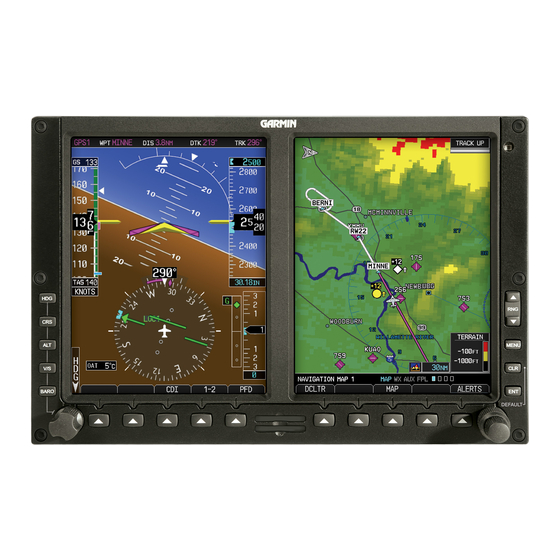
Overview of the G500(H)/G600/G700 TXi display system options.
1.1 Display Layout
Describes the physical layout and components of the Garmin Display Units (GDUs).
1.2 Display Configurations
Illustrates various display configurations for GDU 1060 and GDU 700 series units.
Pilot Interface
Explains how the pilot interacts with the system's controls and displays.
1.4 Unit Power
Details how to power the unit on/off and its power-up behavior.
1.6 Touchscreen
Details the various touch gestures used to operate the touchscreen interface.
GESTURES
Explains common touch gestures like TAP, HOLD, SWIPE, FLICK, and STRETCH.
Databases
Information on supported databases, loading, and updating procedures.
1.9 Database Effective Cycles
Explains how database effectiveness is determined and displayed.
Connectivity
Information on connecting external devices and wireless technologies.
1.16 Flight Stream 510 Setup
Details the setup process for the Flight Stream 510 wireless datacard.
Pilot Settings
Customization options for pilot preferences.
1.19 Display Brightness Control
How to adjust display brightness for optimal visibility.
System Messages
Explains different types of alerts, advisories, and annunciations.
1.26 Alerts Types
Categorizes alert types by urgency and response required.
1.26.1 Warnings & Cautions
Describes immediate attention required warnings and abnormal condition cautions.
1.27 Advisories
Details various system-related messages displayed across connected GDUs.
1.27.4 Emergency Descent Mode Advisories
Advisories specific to the Emergency Descent Mode functionality.
Logs
Information on flight data and exceedance logging.
1.29 Flight Data Logging
Explains the function and requirements for logging flight data.
1.29.1 Exporting to SD Card
Procedure for exporting logged data to an SD card.
Compatible Equipment
Lists the system components and optional interfaces.
1.31 Line Replaceable Units
Details the required and optional LRUs for the TXi system.
1.31.8 Autopilot
Information on autopilot interface functions and compatibility.
1.31.10 Engine Monitoring
Details EIS display for reciprocating and turbine engines.
1.31.15 Traffic
Details compatible traffic systems like TIS-A, TAS/TCAS, and ADS-B.
Primary Flight Display
PFD SETUP
Configuration options and selections for the Primary Flight Display.
2.1 Synchronization Options
Explains how to synchronize settings across multiple TXi PFDs.
2.2 Reference Bugs and Controls
Details how to set and adjust reference bugs and instrument controls.
Flight Instruments
Describes the various flight instruments displayed on the PFD.
2.3 Attitude Indicator
Explains the virtual representation of ground and sky and its components.
2.4 Extreme Attitude Indications
Describes how the PFD indicates extreme pitch and roll attitudes.
2.5 VNAV Guidance Indications
Explains Vertical Navigation guidance displays and data on the PFD.
2.6 Airspeed Indicator
Details the airspeed indicator, its scales, and reference speeds.
2.7 Barometric Altimeter
Explains the barometric altimeter display, units, and tape limits.
2.8 VSI
Describes the Vertical Speed Indicator display formats and automatic changes.
2.9 Horizontal Situation Indicator
Explains the HSI display, its components, and variations.
2.10 CDI
Details the Course Deviation Indicator, its location, and capabilities.
2.11 LDI
Explains how the Lateral Deviation Indicator portrays aircraft position relative to course.
2.12 VDI
Describes how the Vertical Deviation Indicator displays guidance.
2.13 CDI/VDI Preview
Explains the preview option for approach lateral and vertical deviations.
Supplemental Flight Data
Describes supplemental data fields displayed on the PFD.
2.14 Bearing Pointers
Explains the function and display of selectable bearing pointers.
2.15 GPS NAV Status Field
Details the GPS NAV status field displayed on the PFD.
2.16 Relative Wind Data
Explains how the system computes and displays current wind conditions.
2.17 Temp/DALT Display
Describes the dedicated field for outside air temperature or density altitude.
2.18 DME Display
Explains the DME display, including source and distance information.
2.19 Marker Beacon Symbols
Describes the symbols for marker beacon types displayed on the PFD.
2.20 Radar Altitude
Explains how radar altitude displays and the ground band on the altimeter tape.
2.21 Clock/Timer
Describes the generic timer function for counting up time.
Multi-Function Display
MFD SETUP
System selections and configuration options for the Multi-Function Display.
4.1 Nearest Airport Criteria
Filtering criteria for minimum runway length and surface selection.
4.2 MFD Resize Option
Allows changing the size of the MFD screen between 40% and 60% area.
Map
Explains how the Map page depicts aircraft position relative to land and weather.
4.3 Map Interactions
Describes typical map interactions like zoom, pan, and object selection.
4.4 Map Overlays
Details various map overlay selections that can be configured.
4.4.1 Overlay Controls
Explains how control keys enable specified overlay functions.
4.5 Map Detail
Describes how an adjustable slider controls the level of detail on the map.
4.6 Map Setup
Explains where overlay data controls are located and how they function.
4.6.2 Aviation Selections
Details setup options for customizing aeronautical information display.
4.6.3 Smart Airspace
Explains how Smart Airspace feature de-emphasizes non-pertinent airspace.
4.6.4 SafeTaxi
Describes the SafeTaxi database for airport diagrams and hot spot information.
Charts
Explains how the Charts page provides terminal procedures and airport surface diagrams.
4.7 Chart Setup
Details chart setup selections, including information, color scheme, and type.
4.8 Chart Selection
Explains how to select and automatically choose charts based on aircraft status.
4.9 Aircraft Position Icon
Describes how the aircraft position is displayed on charts and airport diagrams.
Active Flight Plan
Displays current flight plan information received from the navigator.
4.10 Edit Data Fields
Explains how to select and arrange flight plan data columns.
Waypoints
Dedicated pages provide waypoint search functions and details.
4.13 Waypoint Information
Describes how waypoint information pages organize search functions and details.
4.14 Waypoint Selection
Explains how to access different waypoint search options.
SiriusXM Audio Entertainment
Provides controls for tuning and presetting satellite radio music channels.
4.15 SiriusXM Audio Activation
Information necessary for activating SiriusXM Satellite Radio services.
4.16 Browse Music Channels
Explains how to browse music channels and select audio categories.
External Video
Describes how the Video page displays live video from mounted cameras.
4.17 SD Video Setup
Details selectable display settings for SD video, including brightness and contrast.
Weather Awareness
WEATHER DISPLAY
Explains how weather data displays as overlays on various pages.
5.1 Weather Products
Lists weather products and their availability across different display modes.
DATALINK WEATHER
Information on datalink weather services and their limitations.
5.2 Weather Page Interactions
Describes how to interact with weather icons and adjust altitude settings.
5.3 Weather Product Age
Explains how weather product age is indicated and its color definitions.
5.4 Precipitation
Details NEXRAD weather radar data, including reflectivity and precipitation intensity.
5.5 Echo Tops
Depicts location, elevation, and direction of NEXRAD radar echoes for storm intensity.
5.6 Clouds
Indicates the altitude of the highest visible portions of clouds.
5.7 Lightning
Describes how lightning strike events are displayed and reported.
5.8 METARs and TAFs
Provides information on current and forecast weather conditions.
5.9 Cell Movement
Displays storm cell locations with direction, speed, and top altitude.
5.10 AIRMETs
Describes AIRMET overlays and types, including textual and graphical advisories.
5.11 Center Weather Advisory
Communicates en route and terminal weather conditions expected within two hours.
5.12 SIGMETs
Details SIGMET overlays and textual reports for significant meteorological information.
5.13 County Warnings
Provides county warnings for continental US, including alerts for fires and natural disasters.
5.14 Cyclone/Hurricane Track
Shows hurricane and tropical storm information, including forecast track.
5.15 AIREP/PIREPs
Describes routine automated and pilot-generated weather reports.
5.16 Surface Analysis
Displays high and low pressure areas and frontal locations on the surface.
5.17 City Forecast
Provides four-day forecasts for major US cities including temperature and sky conditions.
5.18 Winds Aloft
Indicates wind speed and direction for specified altitudes.
5.19 Icing
Presents a graphic view of current icing conditions.
5.20 Turbulence
Classifies turbulence as light, moderate, severe, or extreme.
5.21 Freezing Levels
Color-coded contour lines indicate the altitude of the freezing level.
5.22 TFRs
Identifies airspace temporarily restricted from operating due to various occurrences.
5.23 SiriusXM
Explains how SiriusXM satellites deliver high-resolution weather images.
5.24 FIS-B Weather
Describes the FIS-B weather service and its data transmission limitations.
5.25 Connext Weather
Details Garmin's datalink services for on-demand weather products.
Stormscope
Explains Stormscope lightning data display and features.
5.26 Stormscope Page
Describes the Stormscope page and its features for weather avoidance.
Airborne Weather Radar
Describes how weather radar data displays on dedicated pages or as overlays.
5.28 Weather Radar Page
Explains the Weather Radar page, its controls, and depictions.
5.29 Weather Radar Setup
Details setup options for the weather radar, including sector scan and stabilization.
5.30 Radar Modes
Explains the different radar modes: Standby, Test, Ground, and Weather.
5.31 Radar Controls
Describes how to adjust radar controls like tilt, bearing, scan, and gain.
5.32 Radar Alerts
Explains caution messages for weather radar failures and conditions.
Traffic Awareness
TRAFFIC DISPLAY
Explains how the Traffic page displays intruding traffic relative to the aircraft.
6.1 Traffic Page
Details the display objects and functions on the Traffic page.
TRAFFIC TYPES
Describes different traffic types and their features.
6.2 Traffic Setup
Explains setup options for TIS-A, TAS/TCAS I, and ADS-B traffic systems.
6.2.2 Altitude Filtering
Describes how pilot selectable filters limit traffic display to specific altitude ranges.
6.3 TIS-A
Details Traffic Information Service - Automatic features and setup.
6.4 TAS/TCAS I
Explains Traffic Advisory System and Traffic Alert and Collision Avoidance System I.
6.5 TCAS II
Provides information on Traffic Alert and Collision Avoidance System II.
6.5.1 TCAS II Status Indications
Details the status indications for the TCAS II system.
6.5.2 TCAS II Alerts
Explains TCAS II alerts, including TA and RA notifications and voice alerts.
6.6 ADS-B
Describes Automatic Dependent Surveillance-Broadcast features and setup.
6.6.1 ADS-B Setup Selections
Details ADS-B setup options for status, testing, motion vectors, and altitude filtering.
6.6.2 ADS-B Traffic Symbols
Explains the various symbols used to depict ADS-B traffic information.
6.6.3 ADS-B Traffic Applications
Describes ADS-B traffic applications for airborne, surface, and on-scene modes.
6.6.4 Motion Vectors
Explains how motion vectors represent intruder direction and movement.
6.7 Traffic Alerts
Describes traffic alerts that appear as textual annunciations or pop-up windows.
Terrain Awareness
TERRAIN CONFIGURATIONS
Lists available terrain configurations and controls.
7.1 GPS Altitude for Terrain
Explains how GPS altitude is derived for terrain functions.
7.2 Database Limitations
Details limitations and coverage areas for terrain and obstacle databases.
TERRAIN DISPLAY
Explains the Terrain page and its features for displaying terrain information.
7.3 Terrain Page
Describes the Terrain page and its primary functions for situational awareness.
7.4 Terrain Setup
Details pilot selectable terrain settings, including view, layers, and inhibit functions.
7.5 Terrain Proximity
Describes the terrain proximity features and their graphical representations.
TERRAIN ALERTING
Explains the behavior of alerting functions based on installation settings.
7.6 Alert Types
Lists and describes the different types of terrain alerts.
7.7 Terrain-FLTA
Details the Terrain-FLTA system, its features, and reduced protection mode.
7.7.1 Reduced Protection Mode, Rotorcraft Only
Explains the reduced alerting thresholds for rotorcraft operations.
7.8 TAWS-B
Describes the TAWS-B Class B terrain alerting system and its alerts.
7.9 External TAWS/HTAWS
Explains how external TAWS/HTAWS functions rely on GPS data for terrain map coloration.
Fuel & Engine Indicating System
RECIPROCATING ENGINES
Details the EIS display for reciprocating engines.
8.1 EIS Display
Explains how the EIS displays engine, electrical, and fuel information.
TURBINE ENGINES
Details the EIS display for turbine engines.
8.8 EIS Display
Explains EIS displays for turboprop engines on GDU 700P and GDU 1060.
8.2 EIS Setup
Details EIS setup functions accessible from the Menu or System pages.
8.3 EIS Functions
Describes common EIS display elements like graphical indicators and data fields.
8.4 Gauges
Explains gauge formats and types, including round and bar indicators.
8.4.1 Gauge Types
Lists various gauge labels, units, and their corresponding functions.
8.4.2 Markings & Indications
Explains gauge range indications, color coding, and non-safe range alerts.
8.5 Lean Assist Mode
Details the Lean Assist Mode for identifying peak EGT/TIT temperatures.
8.5.1 Lean Mode Key
Explains how to use the Lean key to enter Lean Assist mode.
8.5.2 Peak Temperature Indications
Describes how the system indicates peak EGT/TIT temperatures during leaning.
8.6 EIS Operations
Outlines EIS operations for different phases of flight.
8.6.1 Initial Setup
Details initial setup operations like customizing settings and calibrating fuel flow.
CALIBRATE FUEL FLOW
Explains the procedure for calibrating the fuel flow meter.
8.11 Gauges
Describes gauge labels and their customization for aircraft configuration.
8.11.5 Gauge Interactions
Explains how to select and interact with user-configurable EIS fields.
8.12 EIS Operations
Outlines EIS operations for different phases of flight.
8.13 Engine Advisories
Specifies values for system advisories on engine parameters.
8.14 Electrical Gauges
Describes electrical gauges for complex electrical systems.
8.15 Fuel Computer
Explains how the fuel computer calculates and displays fuel parameters.
8.15.1 Preset Fuel Quantities
Describes how the fuel computer stores preset fuel amounts for estimation.
8.15.2 Fuel Flow Calibration
Explains the function for comparing estimated fuel used with actual fuel used.
Engine Alerts
Explains engine warnings and cautions requiring immediate action.
Abnormal Operations
BACKUP INSTRUMENTS
Details backup instrument functionality and display modes.
9.1 Display Backup
Explains how display backup mode occurs under specific conditions.
9.1.1 Standby PFD Display Options
Describes options for continuing backup PFD mode or returning to previous display.
9.1.2 Composite Display Backup Mode
Explains changes to PFD layout when entering composite display backup mode.
9.2 Backup Battery
Provides information on the GBB 54 backup battery and its features.
9.2.1 Battery Status Indications
Details battery status indications including icons and timers.
9.2.2 Battery Alerts
Explains caution messages alerting to backup battery status.
9.3 AHRS & ADC Failures
Explains how AHRS and ADC failures affect attitude and heading data.
9.3.1 AHRS and ADC Sensor Selection
Describes pilot controls for selecting AHRS/ADC sensor sources.
9.3.3 GPS Failure
Explains how AHRS uses GPS inputs and what happens when inputs fail.
9.3.4 AHRS Alerts
Details various alerts related to AHRS operation and calibration.
9.3.5 Miscompare & No Compare
Explains miscompare and no compare states for AHRS/ADC sensor data.
9.4 HSI Failure Modes
Describes how the HSI behaves during magnetometer and GPS failures.
9.4.1 GPS Failure
Explains system behavior when GPS position data is lost (dead reckoning mode).
9.4.2 Backup GPS
Details the function and limitations of the backup GPS receiver.
9.5 Emergency Descent Mode
Explains the Emergency Descent Mode for pressurized aircraft.
9.5.1 EDM Activation
Describes how to activate Emergency Descent Mode manually or automatically.
9.5.2 EDM Inhibit
Explains how to inhibit automatic activation and its duration.
9.5.3 EDM Override
Details how to deactivate EDM by disengaging the autopilot.
Qualification
NOTE
Procedures in this section are for ground use only.
10.1 Glove Qualification
Qualifies specific gloves for touchscreen use with GDU units.
GLOVE SELECTION CONSIDERATIONS
Provides factors to consider when selecting gloves for touchscreen use.
GLOVE QUALIFICATION GUIDANCE
Outlines checklists for qualifying gloves for touchscreen operation.
CHECKLIST 1 REQUIRED TASKS
Lists tasks required to qualify a glove for touchscreen interaction.
CHECKLIST 2 NON-REQUIRED TASKS
Lists non-required tasks to assess glove impact on function access.
Need help?
Do you have a question about the G700 TXi and is the answer not in the manual?
Questions and answers