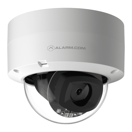
Advertisement
Quick Links
Advertisement

Summarization of Contents
Product Overview
Camera LED Indicator
Details the function of the camera's LED indicator light.
Varifocal Lens
Identifies the varifocal lens component of the camera.
Reset Button
Locates and describes the camera's reset button.
MicroSD Card Slot
Indicates the location of the MicroSD card slot.
RJ45 Ethernet Interface
Highlights the camera's RJ45 Ethernet port for connectivity.
12V DC Power Connector
Shows the connection point for the 12V DC power adapter.
Grounding Terminal
Identifies the camera's grounding terminal.
Camera MAC Address Label
Points out the label containing the camera's MAC address.
LED Status Reference
LED Off: Power Off
Indicates the camera is powered off when the LED is not illuminated.
LED Solid Green: Connected to Alarm.com
Shows the LED status for a successful connection to Alarm.com.
LED Blinking Green: Local Network Connection
Indicates a local network connection when the LED blinks green.
LED Blinking Green/Red: Factory Resetting
Signifies the camera is reverting to factory default settings.
LED Blinking Red: Powering On/Booting
Shows the LED status during camera power-on and booting.
LED Solid Red: No Network Connection
Indicates no local or internet connection when the LED is solid red.
Camera Installation Guide
MobileTech Installation for Service Providers
Steps for installation by service providers using the MobileTech platform.
Ethernet Mode Installation Steps
Procedure for installing the camera using an Ethernet connection.
Detailed Camera Mounting Instructions
Step 1: Remove Camera Cover
Instructions for safely removing the camera's protective cover.
Step 2: Mounting Height and Location Guidelines
Recommendations for optimal mounting height and surface selection.
Step 3: Ensure Clear View Area
Guidance on checking for obstructions impacting night vision.
Step 4: Drill Template and Hole Preparation
Using the drill template to mark and prepare mounting holes.
Step 5: Ground Connection Procedure
Steps for properly connecting the camera to ground.
Step 6: Ethernet, Power, and Ground Cable Connections
Connecting all necessary cables for camera operation.
Step 7: Secure Camera to Mounting Surface
Fastening the camera securely to the chosen mounting surface.
Troubleshooting Common Issues
Troubleshooting Step 1: Power Cycle Camera
Advise to power cycle the camera to resolve connectivity problems.
Troubleshooting Step 2: Reset to Factory Defaults
Instructions for resetting the camera to factory settings if issues persist.
Troubleshooting Step 3: Remove from Previous Account
Guidance on removing the camera from an old account before reinstallation.


Need help?
Do you have a question about the ADC-VC838PF and is the answer not in the manual?
Questions and answers